


Reelmaster 3100−D Hydraulic System (Rev. C)
Page 4 − 99
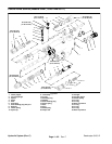
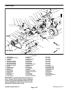
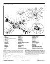
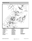
Piston Pump Installation (Fig. 62)
1. If hydraulic fittings were removed, install fittings to
pump using marks made during the removal process to
properly orientate fittings.
2. Place key into pump shaft slot. Slide taper lock bush-
ing onto the piston pump shaft with bushing flange to-
ward pump housing.
3. Make sure that tapered surfaces of pulley and taper
lock bushing are thoroughly clean (no oil, grease, dirt,
rust, etc.).
4. Position pulley to taper lock bushing and align non−
threaded holes of pulley with threaded holes of bushing.
Loosely install three (3) cap screws with lock washers to
bushing and pulley.
5. Install O−rings and hydraulic fittings to their original
positions on the piston pump.
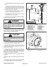
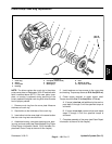
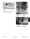
NOTE: If installing a new gear pump to the piston pump,
make sure to remove the plug from the suction port of
the gear pump (Fig. 65). The gear pump suction fitting
must be on the same side as the trunnion of the piston
pump.
6. Remove plugs from the gear pump. Secure O−ring
and gear pump to the piston pump with both flat washers
and socket head screws. Torque fasteners from 27 to 31
ft−lb (37 to 42 N−m).
CAUTION
Support piston and gear pumps when installing
them to the pump mount plate and pump support
to prevent them from falling and causing person-
al injury.
7. Position piston pump to the pump mount plate. Se-
cure pump to the mount plate with both flat washers, cap
screws, and lock nuts. Do not fully tighten fasteners.
8. Secure piston pump to the pump support with both
spacers, washers, and cap screws. Tighten fasteners
securing the piston pump to the pump mount plat and
pump support.
9. Remove plugs from hydraulic hoses. Connect all hy-
draulic hoses as follows:
A. Secure O−rings and hoses to the gear pump.
B. Connect hydraulic suction hose from the hydrau-
lic tank to the barb fitting with hose clamp.
C. Secure O−rings and hydraulic hoses to the piston
pump.
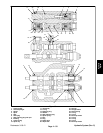
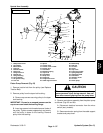
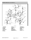
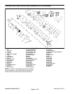
10.Install neutral arm assembly to the piston pump as
follows (Figs. 63 and 64):
A. Position neutral bracket to the mount plate, and
then pump lever to the pump trunnion.
B. Secure pump lever to the piston pump trunnion
with flat washer and cap screw.
C. Secure neutral bracket to the pump mount plate
with flange head screw and flange nut. Secure neu-
tral bracket to the piston pump with both flange head
screws.
D. Connect traction control cable to the pump lever.
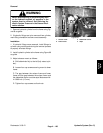
CAUTION
The extension spring is under tension and may
cause personal injury during installation. Use
caution when installing the spring to the pump
lever.
E. Install extension spring to the cable support
bracket and pump lever.
F. Connect electrical connector to the micro switch
(early models).
11.Install traction belt to the pump pulley (see Replace
Traction Belt).
12.Using a straight edge across the lower face of the
pump pulley, verify traction belt alignment across engine
and pump pulleys. Slide pulley and taper lock bushing
on pump shaft so that traction belt and straight edge are
aligned indicating correct position of pump pulley. Se-
cure taper lock bushing in position with set screw.
IMPORTANT: When tightening bushing cap screws,
tighten in three equal steps and in a circular pattern.
13.Secure taper lock bushing by tightening three (3) cap
screws to a torque from 90 to 120 in−lb (10.2 to 13.6
N−m) in three equal steps and in a circular pattern to se-
cure pulley and taper lock bushing.
14.Check that belt alignment is still correct. If needed,
loosen and re−adjust pulley and taper lock bushing loca-
tion on pump shaft to allow for correct belt alignment.
15.Fill hydraulic tank with new hydraulic fluid (see Trac-
tion Unit Operator’s Manual).
16.Adjust traction drive for neutral (see Adjust traction
Drive for Neutral).
Hydraulic
System