


Reelmaster 3100−DHydraulic System (Rev. C)
Page 4 − 98
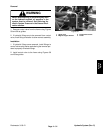
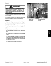
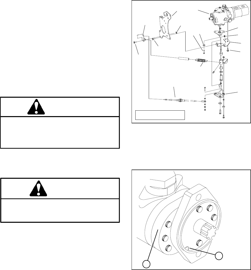
C. Disconnect traction control cable from the pump
lever.
D. Remove both flange head screws securing the
neutral bracket to the piston pump. Remove flange
nut and flange head screw securing the neutral
bracket to the pump mount plate.
E. Remove cap screw and flat washer securing the
pump lever to the piston pump trunnion.
F. Separate pump lever from pump trunnion and
neutral bracket from mount plate.
4. Drain hydraulic oil from hydraulic tank (see Change
Hydraulic Fluid in this section).
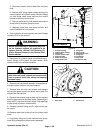
WARNING
Before disconnecting or performing any work
on the hydraulic system, all pressure in the
system must be relieved. See Relieving Hy-
draulic System Pressure in the General Infor-
mation section.
5. Disconnect all hydraulic hoses connected to the hy-
draulic fittings on the piston and gear pumps. Allow
hoses to drain into a suitable container.
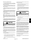
CAUTION
Support piston and gear pumps when removing
them from the pump support and pump mount
plate to prevent them from falling and causing
personal injury.
6. Remove both cap screws, washers, and spacers se-
curing the piston pump to the pump support.
7. Remove both lock nuts, cap screws, and washers
securing the piston pump to the pump mount plate. Pull
pumps from the machine.
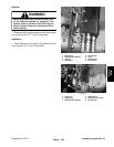
8. Remove both socket head screws and flat washers
securing gear pump to the piston pump. Separate gear
pump and O−ring from the piston pump. Plug openings
of gear pump to prevent contamination.
9. Remove hydraulic fittings and O−rings from the pis-
ton pump.
10.Remove taper lock bushing from the piston pump
shaft.
11.If hydraulic fittings are to be removed from pump,
mark fitting orientation to allow correct assembly.
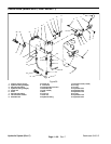
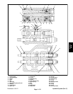
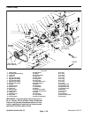
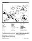
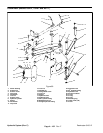
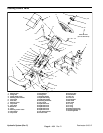
1. Extension spring
2. Cable support bracket
3. Pump lever
4. Traction control cable
5. Neutral bracket
6. Pump mount plate
7. Flange head screw
8. Flange nut
9. Piston pump
10. Flange head screw
11. Flange nut
12. Flat washer
13. Cap screw
14. Pump lever hub
Figure 64
13
6
5
7
9
12
8
10
7
11
2
1
3
4
14
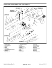
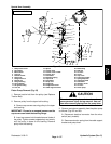
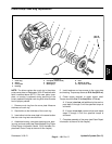
LATER MODELS
Figure 65
1. Gear pump 2. Suction port
2
1