


Reelmaster 3100−D Page 3 − 21 Kubota Diesel Engine
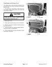
8. Disconnect wire harness and electrical wires from
the following:
A. Engine grounds to the battery and wire harness
(Fig. 30).
B. Glow plug bus and fuel stop solenoid (Fig. 31).
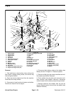
C. High temperature warning switch (Fig. 32).
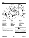
D. High temperature shutdown switch, alternator,
and low oil pressure switch (Fig. 33).
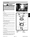
9. Disconnect throttle cable from the support and swiv-
el on the speed control lever (Fig. 30).
10.Disconnect fuel hose from the water/fuel separator
Fig. 30) and front injector nozzle (Fig. 31).
11.Remove traction control cable from the neutral arm
assembly on the piston pump. Remove all hydraulic
hoses from the piston an gear pumps (see Piston Pump
Removal in Chapter 4− Hydraulic System).
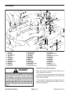
12.Remove cable ties securing the wire harness to the
front lift tab and other engine parts (Fig. 31). Connect
hoist or lift to the front and rear lift tabs (Fig. 31 and 32).
CAUTION
Make sure lift or hoist can support the total
weight of the engine before removing the cap
screws from the rear bracket and engine.
13.Remove flange nut, cap screw, and washer securing
three engine mounts to the engine mounting brackets.
CAUTION
One person should operate lift or hoist while the
other person guides the engine out of the ma-
chine.
IMPORTANT: Make sure not to damage the engine,
fuel and hydraulic lines, electrical harness, or other
parts while removing the engine.
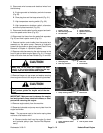
14.Remove engine slowly from the machine.
15.Separate hydrostat and pump mount plate from the
engine as follows:
Note: The cap screw next to the torsion spring does
not have a flat washer with it.
A. Remove traction belt from the engine fly wheel
and hydrostat pulleys (see Traction Belt Replace-
ment).
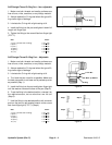
Figure 30
1. Battery ground
2. Wire harness ground
3. Throttle cable
4. Support bracket
5. Speed control lever
6. Fuel hose
2
1
3
4
6
5
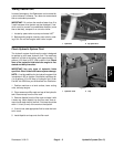
Figure 31
1. Glow plug wire
2. Fuel stop solenoid
3. Fuel hose
4. Front lift tab
1
2
3
4
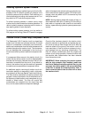
Figure 32
1. Temp. warning switch 2. Rear lift tab
2
1
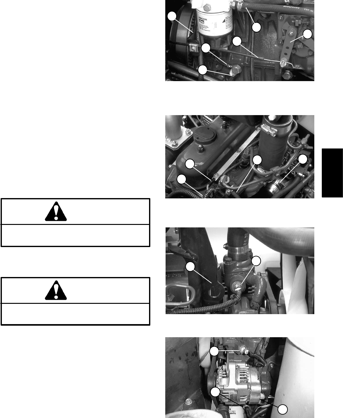
Figure 33
1. Temp. shutdown switch
2. Alternator
3. Low oil press. switch
1
3
2
Kubota Diesel
Engine