


Reelmaster 3100−D
Page 3 − 22
Kubota Diesel Engine
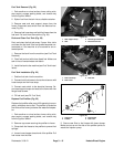
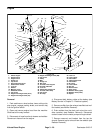
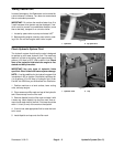
B. Remove five cap screws, four washers, and five
spacers securing the pump mount plate to the en-
gine (Fig. 34).
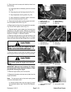
C. Remove four cap screws and hardened washers
securing the right engine mounting bracket and hy-
drostat to the engine.
Installation
1. Install hydrostat and pump mount plate to the engine
as follows:
A. Secure right engine mounting bracket and hy-
drostat to the engine four hardened washers and cap
screws.
Note: Do not install flat washer with cap screw near
the torsion spring to prevent the spring from binding.
B. Secure pump mount plate to the engine with five
spacers, four washers, and five cap screws (Fig. 34).
C. Install traction belt to the engine fly wheel and hy-
drostat pulleys (see Traction Belt Replacement).
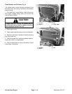
2. Connect hoist or lift to the front and rear lift tabs (Fig.
31 and 32).
CAUTION
One person should operate lift or hoist while the
other person guides the engine into the machine
.
IMPORTANT: Make sure not to damage the engine,
fuel and hydraulic lines, electrical harness, or other
parts while installing the engine.
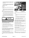
3. Position engine slowly into the machine.
4. Secure all three engine mounts to the engine mount-
ing brackets with cap screw, washer, and flange nut.
5. Secure wire harness to the front lift tab and the en-
gine with cable ties (Fig. 31).
6. Install all hydraulic hoses to the piston and gear
pumps. Install traction control cable to the neutral arm
assembly on the piston pump (see Piston Pump Installa-
tion in Chapter 4− Hydraulic System).
7. Connect fuel hose to the water/fuel separator (Fig.
30) and front injector nozzle (Fig. 31).
8. Install top fan shroud to the radiator. Install reservoir
and bracket to the top fan shroud (see Radiator Installa-
tion).
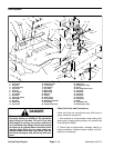
Figure 34
1. Cap screw
2. Spacer
3. Torsion spring
4. Pump mount plate
2
2
2
1
3
1
4
9. Connect wire harness and electrical wires to the fol-
lowing:
A. Engine grounds to the battery and wire harness
(Fig. 30).
B. Glow plug bus and fuel stop solenoid (Fig. 31).
C. High temperature warning switch (Fig. 32).
D. High temperature shutdown switch, alternator,
and low oil pressure switch (Fig. 33).
10.Connect coolant hoses to the water pump and en-
gine block. Make sure drain cock valve is closed. Fill ra-
diator with coolant (see Check Cooling System).
11.Install muffler to the exhaust manifold and muffler
bracket (see Muffler Installation).
12.Connect throttle cable to the support and swivel on
the speed control lever (Fig. 30).
13.Connect both battery cables at the battery (see Bat-
tery Service in Chapter 5 − Electrical system).
14.Install air cleaner to the engine. Connect air hose to
air cleaner and radiator.
15.Adjust throttle cable (see Adjust Throttle Cable).
16.Bleed fuel system (see Bleed Fuel System).
17.Install engine hood to the machine. Close and latch
hood.
18.Adjust traction drive for neutral (see Adjust traction
Drive for Neutral in Chapter 4− Hydraulic System).