


Rev. E
Reelmaster 3100--D Page 7 -- 27 Cutting Units
Removal
1. Park machine on a level surface, lower cutting units,
stop engine, engage parking brake, and remove key
from the ignition switch.
2. Remove cutting unit from the pivot shaft of the front
lift arm (see Cutting Unit Removal).
NOTE: Remove both spacers from the hydraulic cylin-
der shaft clevis when removing the right, front lift arm.
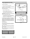
3. Disconnect hydraulic cylinder from the front lift arm
by removing external retaining rings and pin.
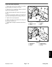
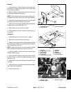
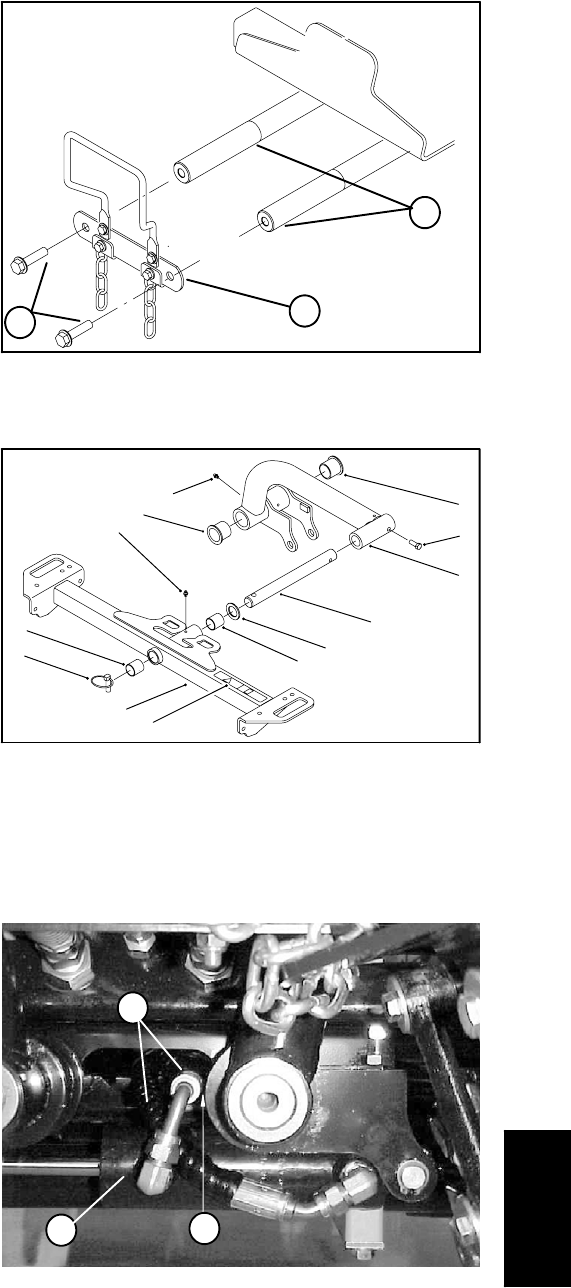
4. Remove bothflange head screws and pivot shaftlink
from the lift arm pivot shafts (Fig. 33).
5. Slide lift arm off the lift arm pivot shaft.
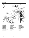
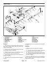
6. Disassemble lift arm as necessary using Figure 34
as a guide.
Installation
1. Assemble lift arm using Figure 34 as a guide.
2. Slide lift arm onto the lift arm pivot shaft.
3. Secure pivot shaft link with both flange head screws
to the lift arm pivot shafts. Torque flange head screws to
70 Ft--lb (95 N--m) (Fig. 33).
NOTE: Install both spacers to the hydraulic cylinder
shaft clevis when installing the right, front lift arm.
4. Secure hydraulic cylinder to the lift arm with pin and
external retaining rings.
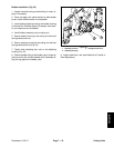
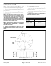
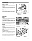
5. Route hydraulic hoses so they clear the lift arm by
0.04 to 0.12 inch (1.0 to 3.0 mm) when the lift arm is fully
raised (Fig. 35).
6. Adjust lift arms to proper clearance (see Adjust Front
Lift Arms).
7. Install cutting unit to the pivot shaft of the front lift arm
(see Cutting Unit Installation).
8. Grease front lift arm.
1. Flange head screw
2. Pivot shaft link
3. Lift arm pivot shaft
Figure 33
2
3
1
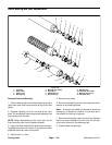
1. Lynch pin
2. Cutting unit pivot shaft
3. Carrier frame
4. Thrust washer
5. Lift arm (LH)
6. Lift arm (RH) (not shown)
7. Cap screw
8. Bushing
9. Bushing
10. Grease fitting
11. Pinch point decal
Figure 34
2
6
5
7
4
1
3
10
9
8
9
12
11
8
1. Hydraulic hoses
2. Hydraulic cylinder
3. Hydraulic cylinder
Figure 35
1
2
3
Cutting Units