


Units
DPA Cutting
Reelmaster 3100--D
DPA Cutting Units (Rev. G)
Page 8 -- 37
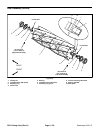
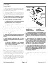
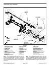
Disassembly (Fig. 38)
1. Position machine on a clean and level surface, lower
cutting units, stop engine, engage parking brake and re-
move key from the ignition switch.
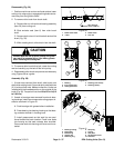
2. To remove roller brush from brush shaft:
A. Remove the non--driven brush bearing assembly
(item 30) from cutting unit.
B. Slide excluder seal (item 6) from roller brush
shaft.
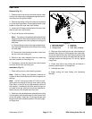
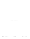
C. Remove lock nutand J--bolt from both ends ofthe
brush (Fig. 39).
D. While rotating brush, slide brush from the shaft.
CAUTION
Contact with the reel or other cutting unit parts
can result in personal injury. Use heavy gloves
when handling the cutting reel.
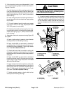
3. To remove roller brush drive belt, rotate the cutting
reel and carefully pry the belt off the drive pulley.
4. Disassemble roller brush components as necessary
using Figures 38 as a guide.
Assembly (Fig. 38)
1. If brush was removed from shaft, slide brush onto
shaft whilerotating brush.Secure brush toshaft withtwo
(2) J--bolts and lock nuts. Make sure that the J--bolts are
installed with the threaded portion on the outside of the
brush (Fig. 39).Torque lock nuts from20 to 25 in--lb (2.3
to 2.8 N--m).
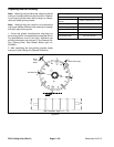
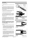
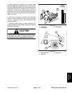
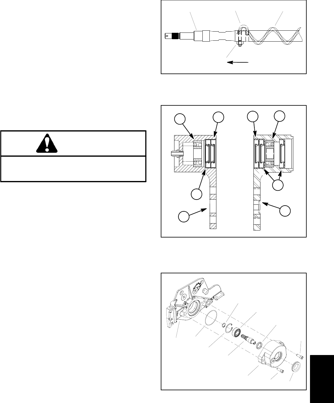
2. If seals or bearings were removed from brush bear-
ing housings, install new components noting proper ori-
entation as shown in Figure 40.
A. Pack bearings with grease before installation.
B. Press bearing into bearing housing so that bear-
ing contacts shoulder in housing bore.
C. Install grease seals so that seal lips are posi-
tioned toward the brush location. Press inner seals
into housing so that seal contacts bore shoulder.
Press outer seals into housing until inner seal is con-
tacted.
1. Roller brush shaft
2. J--bolt
3. Roller brush
4. Lock nut
Figure 39
1
2
3
4
20 to 25 in--lb
(2.3 to 2.8 N--m)
1. Bearing
2. Inner grease seal
3. Outer grease seal
4. Housing (non--driven)
5. Housing (driven)
Figure 40
2
2
1
1
4
5
3
3
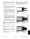
1. Bearing housing
2. Drive shaft
3. Ball bearing
4. Grease seal
5. Retaining ring
6. Snap ring
7. O--ring
8. Side plate
9. Socket head screw
10. Grommet
Figure 41
1
2
3
4
5
6
9
10
7
8
9