Reelmaster 3100−D Hydraulic System (Rev. C)
Page 4 − 69
Rear Wheel Removal
1. Park machine on a level surface, lower cutting units,
stop engine, engage parking brake, and remove key
from the ignition switch.
WARNING
Before jacking up the machine, review and follow
Jacking Instructions in Chapter 1 − Safety.
2. Jack up rear of machine enough to allow the removal
of the rear wheel.
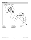
3. Remove rear tire and rim assembly from machine.
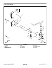
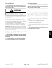
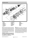
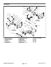
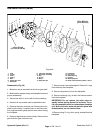
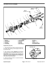
4. Remove rear wheel motor with wheel hub attached
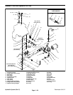
from the rear fork using Figure 43 as guide.
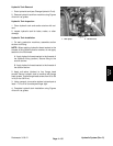
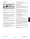
5. Secure wheel hub in a vise. Loosen but do not re-
move lock nut that secures wheel hub to wheel motor.
IMPORTANT: DO NOT hit wheel hub, wheel hub
puller or wheel motor with a hammer during wheel
hub removal or installation. Hammering may cause
damage to the wheel motor.
6. Using hub puller (see Special Tools), loosen wheel
hub from wheel motor.
7. Remove wheel hub and motor from vise. Remove
lock nut and hub from motor shaft. Locate and retrieve
woodruff key.
8. If hydraulic fittings are to be removed from wheel mo-
tor, mark fitting orientation to allow correct assembly.
Rear Wheel Installation
1. If hydraulic fittings were removed, install fittings to
reel motor using marks made during the removal pro-
cess to properly orientate fittings.
2. Thoroughly clean wheel motor shaft and wheel hub
taper.
3. Clamp wheel hub in a vise. Install woodruff key into
the wheel motor shaft. Slide motor shaft into hub and se-
cure with lock nut. Torque lock nut from 250 to 350 ft−lb
(339 to 474 N−m). Remove wheel motor and hub from
vise.
4. Install wheel motor to the rear fork using Figure 43 as
guide.
5. Install tire and rim assembly to machine.
6. Lower the machine to the ground.
7. Torque rear wheel lug nuts from 45 to 65 ft−lb (61 to
88 N−m).
8. Make sure hydraulic tank is full. Add correct oil if nec-
essary (see Operator’s Manual).
Hydraulic
System


