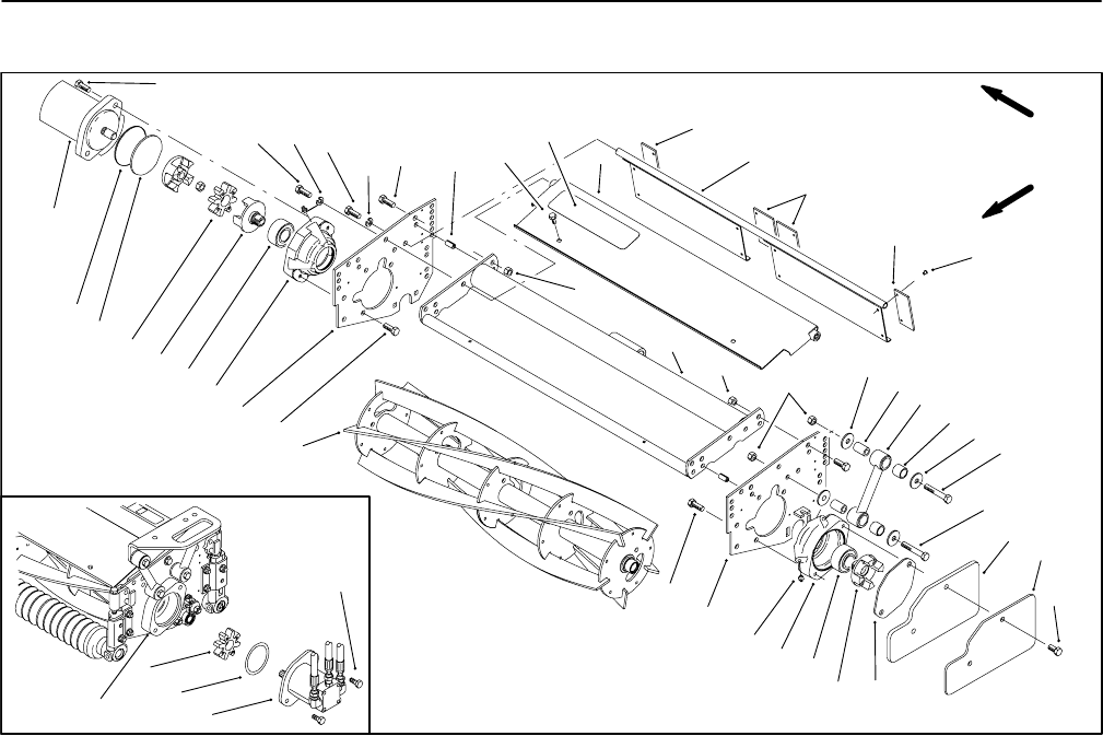
Reelmaster 3100−DPage 7 − 16Cutting Units
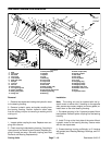
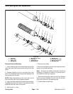
Reel Motor Removal and Installation
1. Reel
2. Cap screw
3. Not used
4. Cap screw
5. Lock washer
6. Side plate (RH)
7. Roll pin
8. Lock nut
9. Hex nut
10. Waring decal
11. Front grass guard
12. Frame assembly
13. Rear grass guard
14. Flange nut
15. Side plate (LH)
16. Washer
17. Spacer
18. Link
19. Bushing
20. Cap screw
21. Cap screw
22. Cap screw
23. Not used
24. Reel coupler (LH)
25. Grease fitting
26. Hex flange head screw
27. Bearing housing
28. Bearing
29. Reel coupler (RH)
30. Spider coupler
31. Not used
32. Not used
33. Cover gasket
34. O−ring
35. Shipping plug
36. Weight (3.5 lbs)
37. Weight (2.0 lbs)
38. Rubber side cover
39. Rubber center cover
40. Rivet
41. Hydraulic motor
Figure 22
33
34
35
36
37
1
2
4
5
6
7
8
9
10
16
17
18
19
20
21
22
24
25
26
27
28
29
30
11
12
13
14
15
2
5
2
38
38
39
40
8
16
26
27
28
41
FRONT
RIGHT
30
34
2
41
27
Removal
1. Remove two capscrews holding the hydraulic motor
to the bearing housing.
2. Remove hydraulic motor and spider coupling from
the bearing housing. Position hydraulic motor away
from the cutting unit prior to removing or working on the
cutting unit.
Inspection
1. Inspect spider coupling for wear. Replace worn cou-
pling with new one.
2. Check coupling inside bearing housing. If coupling is
loose remove and check for worn threads. Replace cou-
pling if threads are worn. Reinstall coupling (see Reel
Removal and Bearing Replacement).
Installation
Note: The cutting unit can be installed with the hy-
draulic motor on either side. If installing on the opposite
side, remove cap screws, weights, and cover gasket; re-
install them on the other bearing housing.
1. Dip spider coupling in No. 2 general purpose lithium
base grease. Reinstall spider coupling into the bearing
housing.
2. Install O−ring on the front plate of the motor. Mount
hydraulic motor to the bearing housing. Secure motor
with the two capscrews.
3. Grease bearing housing sufficiently to fill housing
with grease (see Greasing Bearings, Bushings, and Piv-
ot Points).


