


Reelmaster 3100−D Hydraulic System (Rev. C)
Page 4 − 75
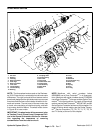
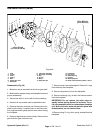
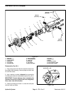
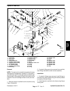
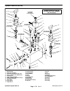
Inspection (Fig. 46)
1. Remove all nicks and burrs from all parts with an
emery cloth.
CAUTION
Use eye protection such as goggles when using
compressed air.
2. Clean all parts with solvent. Dry all parts with com-
pressed air.
3. Inspect drive gear shaft for a broken or chipped key-
way.
4. Inspect drive gear and idler gear shafts at the bush-
ing points and seal area for rough surfaces and exces-
sive wear.
5. Replace drive gear or idler gear if the shaft diameter
in the bushing area measures less than 0.748 in. (19.0
mm). A single gear may be replaced separately.
6. The drive gear and idler gear face should be free of
excessive scoring and wear.
7. Replace drive gear or idler gear if gear width is less
than 1.140 in. (29.96 mm).
8. Make sure that retaining rings are in the grooves on
both sides of the gear for both the drive gear and idler
gear.
9. Break sharp edges of gear teeth with emery cloth.
10.Replace backplate and frontplate if bushing inside
diameters exceed 0.755 in. (19.2 mm). The bushings
are not available as replacement items.
11.The face of the backplate and frontplate should be
free of excessive scoring. Replace if scoring a depth of
0.0015 in. (0.038 mm).
12.Replace body if the inside diameter of the gear pock-
ets exceeds 1.713 in. (43.5 mm).
13.Make sure both plugs are secure if they or the back-
plate is not being replaced.
Reassembly (Fig. 46)
1. If replacing the relief valve assembly, install ball,
spring, shim, O−ring, and plug into the backplate. Hand
tighten plug and then torque from 10 to 12 ft−lb (13.6 to
16.3 N−m).
2. Coat O−ring lightly with petroleum jelly and install in
groove on the front plate.
3. Apply a thin coat of petroleum jelly to both gear pock-
ets of the body. Install alignment pin into body.
4. Align matchmarks and slip body onto front plate until
alignment pin is engaged.
5. Dip idler gear and drive gear into clean hydraulic oil
and slip into front plate bushings.
6. Coat O−ring lightly with petroleum jelly and install in
groove on the back plate.
7. Install alignment pin into back plate.
8. Align matchmarks and slip back plate over gear
shafts onto body until alignment pin is engaged.
9. Hand tighten cap screws. Torque cap screws in a
crisscross pattern from 25 to 28 ft−lb (33.9 to 38.0 N−m).
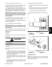
10.Place washer over the drive shaft into the front plate
housing. Apply a liberal coat of hydraulic oil to the oil
seal. Install oil seal over the drive shaft being careful not
to cut the rubber seal lips.
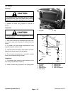
11.Place 1−1/16 inch O.D. sleeve over the drive shaft
and press in the oil seal until the retaining ring groove
appears.
12.Press retaining ring into the housing using the sleeve
until it seats in the groove.
Hydraulic
System