


Reelmaster 3100−DPage 5 − 44Electrical Systems (Rev. C)
2. Conduct a hydrometer test of the battery electrolyte.
IMPORTANT: Make sure the area around the cells is
clean before opening the battery caps.
A. Measure the specific gravity of each cell with a
hydrometer. Draw electrolyte in and out of the
hydrometer barrel prior to taking a reading to warm−
up the hydrometer. At the same time take the tem-
perature of the cell.
B. Temperature correct each cell reading. For each
10
o
F (5.5
o
C) above 80
o
F (26.7
o
C) add 0.004 to the
specific gravity reading. For each 10
o
F (5.5
o
C) be-
low 80
o
F (26.7
o
C) subtract 0.004 from the specific
gravity reading.
Example: Cell Temperature 100
o
F
Cell Gravity 1.245
100
o
F minus 80
o
F equals 20
o
F
(37.7
o
C minus 26.7
o
C equals 11.0
o
C)
20
o
F multiply by 0.004/10
o
F equals 0.008
(11
o
C multiply by 0.004/5.5
o
C equals 0.008)
ADD (conversion above) 0.008
Correction to 80
o
F (26.7
o
C) 1.253
C. If the difference between the highest and lowest
cell specific gravity is 0.050 or greater or the lowest
cell specific gravity is less than 1.225, charge the bat-
tery. Charge at the recommended rate and time giv-
en in Charging or until all cells specific gravity is
1.225 or greater with the difference in specific gravity
between the highest and lowest cell less than 0.050.
If these charging conditions can not be met, replace
the battery.
3. Perform a high−discharge test with an adjustable
load tester.
This is one of the most reliable means of testing a battery
as it simulates the cold−cranking test. A commercial bat-
tery load tester is required to perform this test.
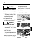
CAUTION
Follow the manufacturer’s instructions when us-
ing a battery tester.
A. Check the voltage across the battery terminals
prior to testing the battery. If the voltage is less than
12.4 VDC, recharge the battery.
B. If the battery has been charged, apply a 150 amp
load for 15 seconds to remove the surface charge.
Use a battery load tester following the manufactur-
er’s instructions.
C. Make sure battery terminals are free of corrosion.
D. Measure the temperature of the center cell.
E. Connect a battery load tester to the battery termi-
nals following the manufacturer’s instructions.
Connect a digital multimeter to the battery terminals.
F. Apply a test load of one half the Cranking Perfor-
mance (see Battery Specifications) rating of the bat-
tery for 15 seconds.
G. Take a voltage reading at 15 seconds, then re-
move the load.
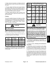
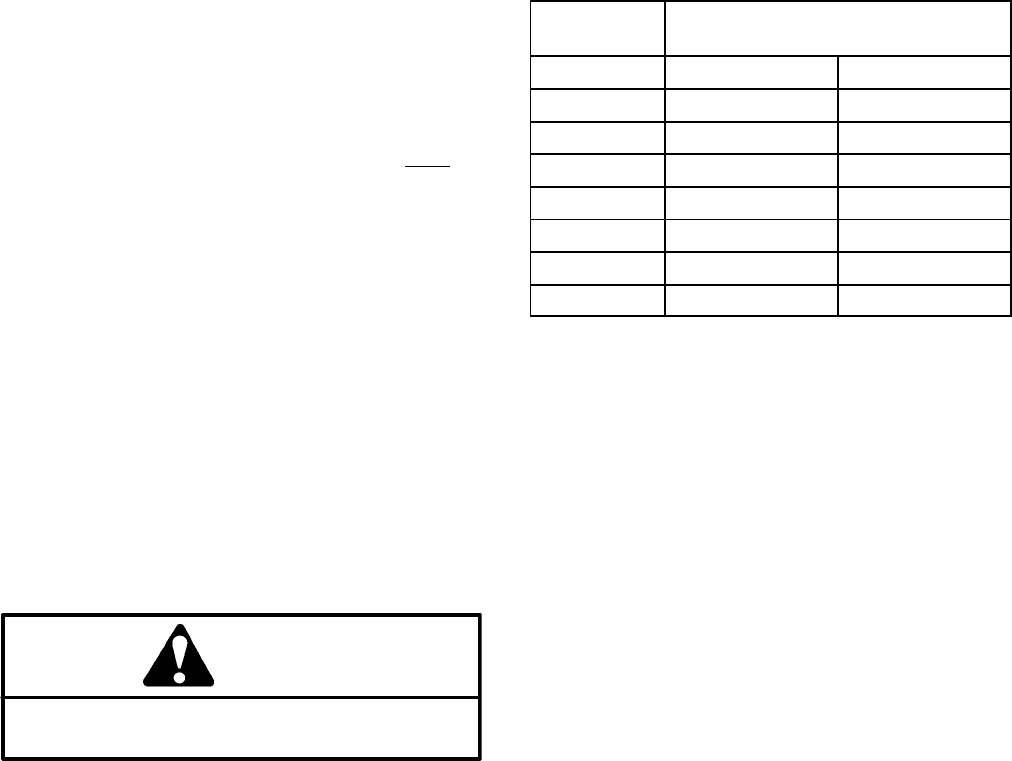
H. Using the table below, determine the minimum
voltage for the cell temperature reading.
Minimum
Voltage
Battery Electrolyte
Temperature
9.6 70
o
F (and up) 21.1
o
C (and up)
9.5 60
o
F 15.6
o
C
9.4 50
o
F 10.0
o
C
9.3 40
o
F 4.4
o
C
9.1 30
o
F −1.1
o
C
8.9 20
o
F −6.7
o
C
8.7 10
o
F −12.2
o
C
8.5 0
o
F −17.8
o
C
I. If the test voltage is below the minimum, replace
the battery. If the test voltage is at or above the mini-
mum, return the battery to service.
Installation
IMPORTANT: To prevent possible electrical prob-
lems, install only a fully charged battery.
1. Make sure ignition and all accessories are off.
2. Make sure battery compartment is clean and re-
painted if necessary.
3. Make sure all battery cables and connections are in
good condition and battery retainer has been repaired
or replaced.
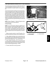
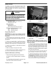
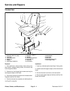
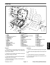
4. Place battery in its compartment. Make sure battery
is level and flat. Connect positive cable connector onto
positive battery post. Tighten cap screw and lock nut
with two wrenches.
IMPORTANT: The nut must be on top of the battery
retainer during installation to prevent the cap screw
from hitting hydraulic hard lines when the sidewind-
er is shifted.
5. Secure battery retainer. Do not overtighten to pre-
vent cracking or distorting the battery case.