


Rev. E
Reelmaster 3100--DHydraulic System (Rev. C)
Page 4 -- 82
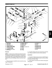
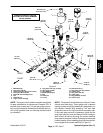
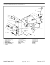
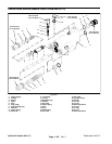
8. Install rotary handle (Fig. 52) (manifold shown in Fig.
51) :
A. Place handle baseon flow control valve and posi-
tion alignment mark on base with number 1 on man-
ifold. Secure base with two (2) set screws. Apply a
light coating of grease to chamfer on top of base to
ease seal installation.
B. Make sure that sleeve bearing is in handle cap. If
necessary, press sleeve bearing into cap. Install lip
seal on cap w ith seal lip facing down.
C. Place bushing onto cartridge valve stem. Use a
small amount of grease to keep bushing toward the
topofthevalvestem.
D. Place compression spring and detent pin into
handle cap. Use a small amount of grease to hold
detent pin in place.
E. Make sure that flow control v alve is closed by ro-
tating valve stem fully clockwise. During handle
installation, DO NOT rotate valve stem or speed ad-
justment will be incorrect.
F. Press handle cap onto valve stem with arrow on
cap pointingto number 9on manifold.Make sure that
detent pin and spring stay positioned in cap.
G. While pressing on the cap to keep the lip seal in
place, rotate cap in a clockwise direction until the ar-
row on the cap aligns with number 1 on the manifold.
By rotating the cap clockwise, the valve will remain
closed. Install screw to retain cap.
H. Make sure that alignment marks onc ap and base
are inline and thatarrow on capis pointing tonumber
1 on manifold. Tighten two (2) set screws to secure
handle cap.
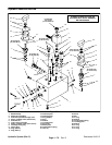
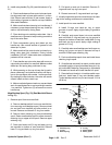
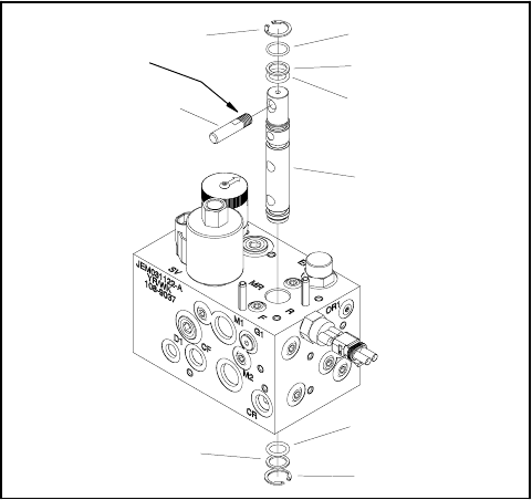
Mow/Backlap Spool (Fig. 53) (Reel Manifold Shown
in Fig. 51)
1. Remove spool from mow manifold:
A. Remove backlap switch from mow manifold be-
fore removing mow/backlap spool. Remove dowel
pin and ball from manifold port after switch is re-
moved. Remove and discard O--ring from switch.
B. Remove lower retaining ring from mow/backlap
spool. Raise mow/backlap spool to allow access to
retaining ring on upper end of spool. Remove upper
retaining ring.
C. Push spool down until O--ring and back--up ring
are exposed on bottom of mow manifold. Remove
lower O--ring and back--up ring from spool.
D. Pull spool up and out of manifold. Remove O--
rings and back--up ring from spool.
E. Discard removed O--rings and back--up rings.
2. Visually inspect the spool and manifold port for dam-
age to the sealing surfaces and contamination.
3. Install spool into mow manifold:
A. Install O--rings and back--up ring to upper
grooves on spool. Apply a light coating of grease to
O--rings.
B. Carefully push spool down into mow manifold
port until lower O--ring and back--up ring groove is
exposed on bottom of manifold. Install lower O--ring
and back--up ring to spool. Apply a light coating of
grease to O--ring.
C. Carefully raise mow/backlap spool until upper re-
taining ring groove on spool is exposed on top of
manifold. Install upper retaining ring.
D. Push mow/backlap spool down and install lower
retaining ring to spool.
E. If handle w as removed from spool, position spool
so handle location of spool is between stop pins. Ap-
ply Loctite 603 Retaining Compound (or equivalent)
to threads on handle and install handle into spool.
F. Place ball and dowel pin in backlap switch man-
ifold port. Install new O--ring onto backlap switch.
Thread backlap switch into port and torque 15 ft--lb
(20 N--m).
1. Retaining ring
2. O--ring
3. Back--up ring
4. O--ring
5. Spool handle
6. Rotary spool
Figure 53
1
2
3
4
5
6
1
3
4
Loctite 603