


Rev. CReelmaster 3100−D Page 6 − 3 Wheels, Brakes,and Miscellaneous
Adjustments
Adjust Brake
CAUTION
Before and after adjusting the brakes, always
check the brakes in a wide open area that is flat
and free of other persons and obstructions.
1. Park machine on a level surface, lower cutting units,
stop engine, and remove key from the ignition switch.
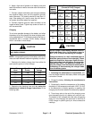
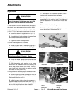
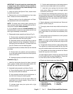
2. Adjust parking brake lever until a force of 30 to 40 lbs
(133 to 178 N) is required to actuate lever. To adjust:
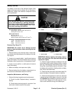
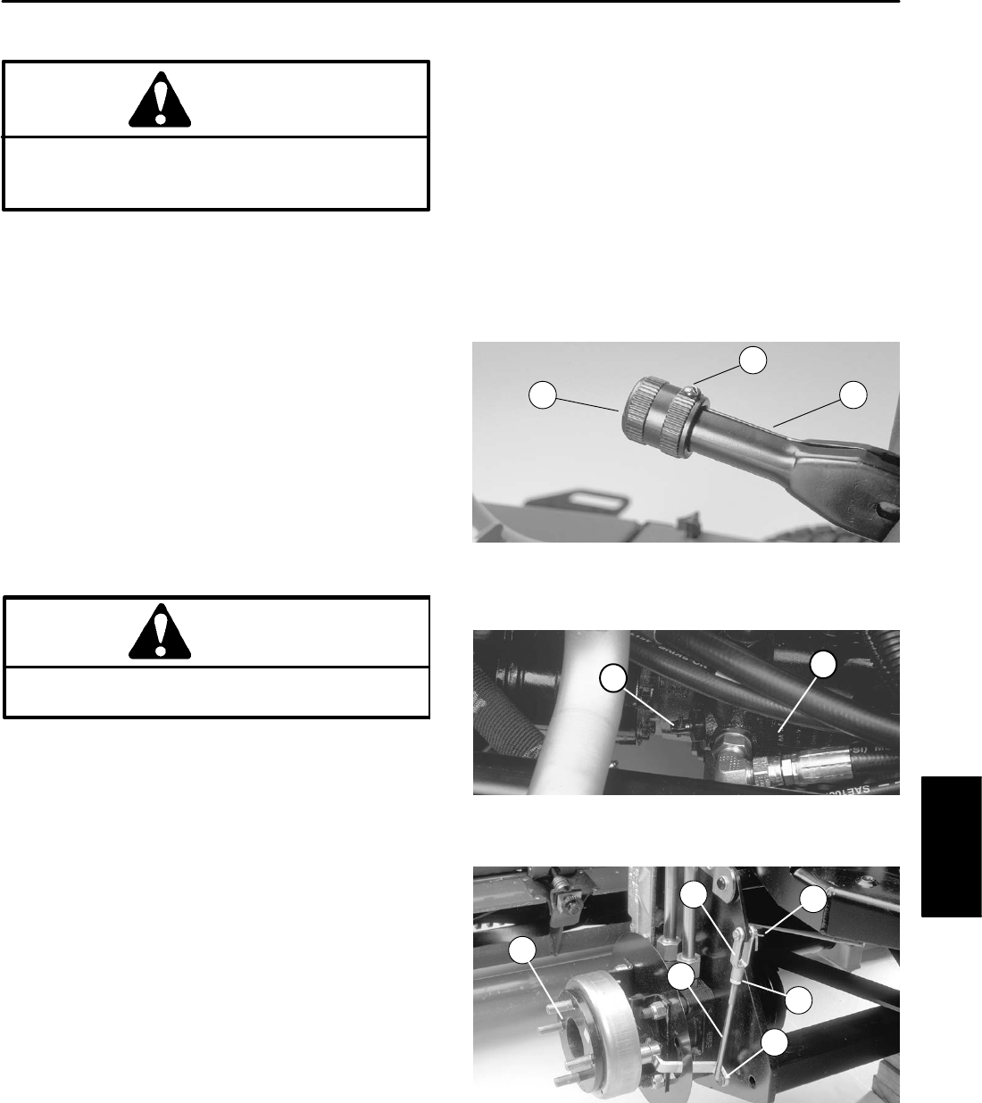
A. Loosen set screw on adjustment knob (Fig. 2).
B. Turn adjustment knob clockwise to increase force
and counterclockwise to decrease force.
C. Tighten set screw after adjustment.
3. Check brake adjustment as follows:
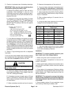
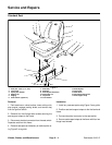
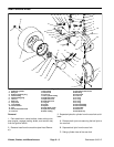
A. Rotate by−pass valve on the piston pump 90 de-
grees to allow front wheels to turn freely (Fig. 3).
CAUTION
Before jacking up the machine, review and follow
Jacking Instructions in Chapter 1 − Safety.
B. Chock rear wheel. Jack up both front wheels and
support the machine with hardwood blocks.
C. With the parking brake applied, use a torque
wrench on the wheel hub lock nut to identify the
break away torque at each front wheel. The mini-
mum break away torque with the parking applied
should be 270 ft−lb (366 N−m).
4. If adjustment is necessary, adjust brakes as follows:
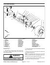
A. Remove both front wheel assemblies from the
machine (see Front Brake and Wheel Removal in the
Service and Repairs section).
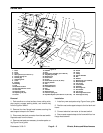
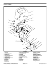
B. Adjust brakes by turning clevis to increase or de-
crease shoe pressure on the brake drum (Fig. 4).
Make sure that brake shoes do not drag against
drums with the parking brake lever released.
C. If brakes can not be adjusted properly, repair or
replace brake components as necessary.
D. After adjustment is complete, install front wheel
assemblies to the machine (see Front Brake and
Wheel Installation in the Service and Repairs sec-
tion).
E. Lower front wheels to the ground.
F. Before starting engine, close by−pass valve on
pump by rotating it 90 degrees (Fig. 3).
1. Set screw
2. Adjustment knob
3. Brake lever
Figure 2
1
2
3
1. Piston pump 2. By−pass valve
Figure 3
2
1
1. Clevis
2. Adjustment rod
3. Brake lever
4. Wheel hub
5. Cotter pin
6. Jam nut
Figure 4
1
4
6
5
3
2
Wheels, Brakes,
and Miscellaneous