


Rev. E
Reelmaster 3100--D Hydraulic System (Rev. C)
Page 4 -- 79
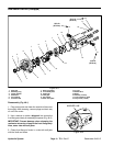
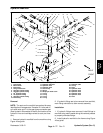
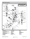
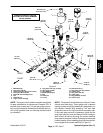
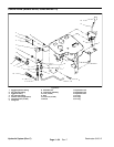
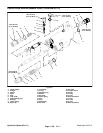
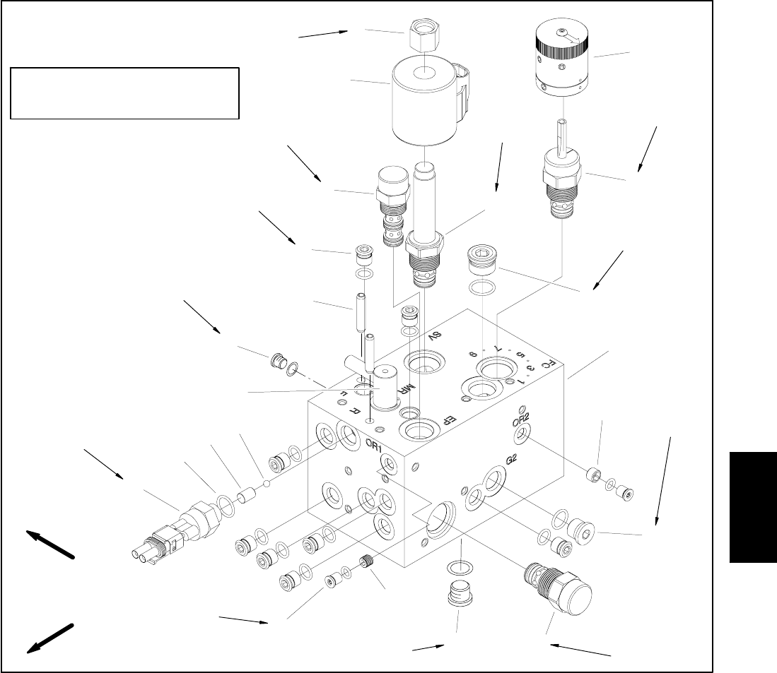
1. Manifold body
2. Plug (Zero Leak #8)
3. Rotary cartridge valve (flow control)
4. Rotary handle assembly
5. Solenoid relief cartridge valve
6. Nut
7. Solenoid coil
8. Logic control cartridge
9. Plug (Zero Leak #4) (10 used)
10. Spring pin (2 used)
11. Plug (SAE #4)
12. Mow/backlap spool
13. Ball
14. Dowel pin
15. O--ring
16. Ball switch (N.C.)
17. Plug (Zero Leak #2) (2 used)
18. Orifice (.020)
19. Plug (Zero Leak #6)
20. Check valve
21. Plug (SAE #6) (2 used)
22. Orifice (.073)
Figure 51
5
9
2
1
6
4
3
7
8
10
12
11
13
14
16
15
17
18
19
20
21
40 ft--lb
(54 N--m)
48 to 60 in--lb
(5.4 to 6.7 N--m)
20 ft--lb
(27 N--m)
120 in--lb
(13.5 N--m)
25 ft--lb
(34 N--m)
25 ft--lb
(34 N--m)
41 ft--lb
(55 N--m)
220 in--lb
(25 N--m)
120 in--lb
(13.5 N--m)
15 ft--lb
(20 N--m)
90 in--lb
(10.1 N--m)
198 in--lb
(22 N--m)
22
FRONT
RIGHT
HYDRAULIC MANIFOLD USED ON
MACHINES WITH SERIAL NUMBERS
ABOVE 260000000
NOTE: The ports on the hydraulic manifold are marked
for easy identification of components. Example: FC1 is
the flow control valve and P1 is the gear pump connec-
tion port (See Hydraulic Schematics to identify the func-
tion of the hydraulic lines and cartridge valves at each
port location).
NOTE: Thehydraulic manifold shownin Figure 51 uses
several zero leak plugs. These plugs have a tapered
sealing surface on the plug head that is designed to re-
sist vibration induced plug loosening. The zero leak
plugs also have an O--ring to provide a secondary seal.
If zero leak plug removal is necessary, lightly rap the
plug head using a punch and hammer before using an
allen wrench to remove the plug: the impact w ill allow
plug removal with less chance of damage to the socket
head ofthe plug. Wheninstalling plugs intothe manifold,
torque plugs to the values identified in Figure 51.
Hydraulic
System