


Rev. E
Reelmaster 3100--DHydraulic System (Rev. C)
Page 4 -- 80
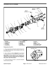
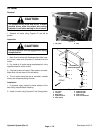
Solenoid Operated, Relief and Logic Control C ar-
tridge Valves
1. Make sure the manifold is clean before removing the
cartridge valve and seal kit.
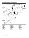
Note: On manifold shown in Figure 50, solenoid coil
has an O--ring on each side of the coil.
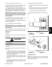
2. If solenoid valve is to be removed from manifold, re-
move nut securing solenoidto the cartridge valve. Care-
fully slide solenoid and O-rings (if equipped) off the
valve.
IMPORTANT: Use care when removing cartridge
valves. Slight bending or distortion of the stem tube
can cause binding and malfunction. Make sure that
deep well socket fully engages the valve base.
3. Remove cartridge valve from manifold with a deep
well socket wrench. Remove seal kit from valve.
4. Visually inspect the manifoldport and cartridge valve
for damage to sealing surfaces, damaged threads, and
contamination.
A. Contamination may cause valves to stick or hang
up. Contaminationcan becomelodged insmall valve
orifices or seal areas causing valve malfunction.
B. If valve sealing surfaces appear pitted or dam-
aged, the hydraulic system may be overheating or
there may be water in the system.
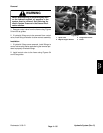
CAUTION
Use eye protection such as goggles when using
compressed air.
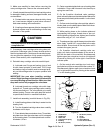
5. Cleaning cartridge valves:
A. For non--solenoid operated valves:
Submerge valve in clean mineral spirits to flush out
contamination. If valve design allows, use a probe to
push the internal spool in and out 20 to 30 times to
flush out contamination. Particles as fine as talcum
powder can affect the operation of high pressure hy-
draulic valves. Clean and dry cartridge with com-
pressed air.
B. For solenoid operated valves:
Temporarily install solenoid on cartridge valve and
connecta 12volt powersource tothe solenoid.While
energized, flush out any contamination with a non-
flammable aerosol brake cleaner. De-energize the
solenoid. Repeat the flush while energized proce-
dure 5 or 6 times. Particles as fine as talcum powder
can affect the operation of high pressure hydraulic
valves. Remove solenoid from cartridge.
6. Reinstall the cartridge valve into the manifold:
A. Lubricate new O-rings and backup rings of seal
kit with clean hydraulic oil and install on cartridge.
The O-rings and backup rings must be arranged
properly on the cartridge valve for proper operation
and sealing.
IMPORTANT: Use care when installing cartridge
valves. Slight bending or distortion of the stem tube
can cause binding and malfunction. Make sure that
deep well socket fully engages the valve base.
B. Lubricate threads on cartridge valve with clean
hydraulic oil. Thread cartridge valve carefully into
correct manifold port. The valve should go in easily
without binding.
C. Torque cartridge valve using a deep well socket
to specification shown in manifold illustration.
Note: On manifold shown in Figure 50, solenoid coil
has an O--ring on each side ofthe coil. Also,on this man-
ifold, apply Loctite242 or equivalent tothe threads ofthe
valve before installing the coil nut.
7. For solenoid valve, install solenoid coil and O-rings
(if equipped) tothe cartridge valve. Torque nut to specifi-
cation shown in manifold illustration.
8. If problems still exist, remove valve and clean again
or replace valve.
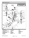
Rotary Cartridge Valves
1. Remove knob assembly (manifold shown in Fig. 50):
A. Unscrew and remove knob. Remove both jam
nuts.
B. Slide off indicator plate being careful not to lose
springs. Remove spring.
C. Loosen set screw and slide detent plate off the
cartridge valve stem.
D. Remove locating plate with pin from the cartridge
valve stem and manifold.
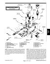
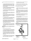
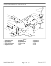
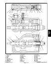
2. Remove rotary handle (manifold shown in Fig. 51)
(Fig. 52):
A. Loosen two (2) set screws that secure handle
cap. Remove screw and then lift handle cap from
valve.
B. Locate and retrieve detent pin, compression
spring, bushing and lip seal. The sleeve bearing
should stay in the cap.
C. Loosen two (2) set screws that secure handle
base to flow control valve and remove base.