


PXA250 and PXA210 Applications Processors Design Guide 7-3
I2C
.
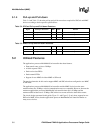
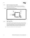
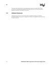
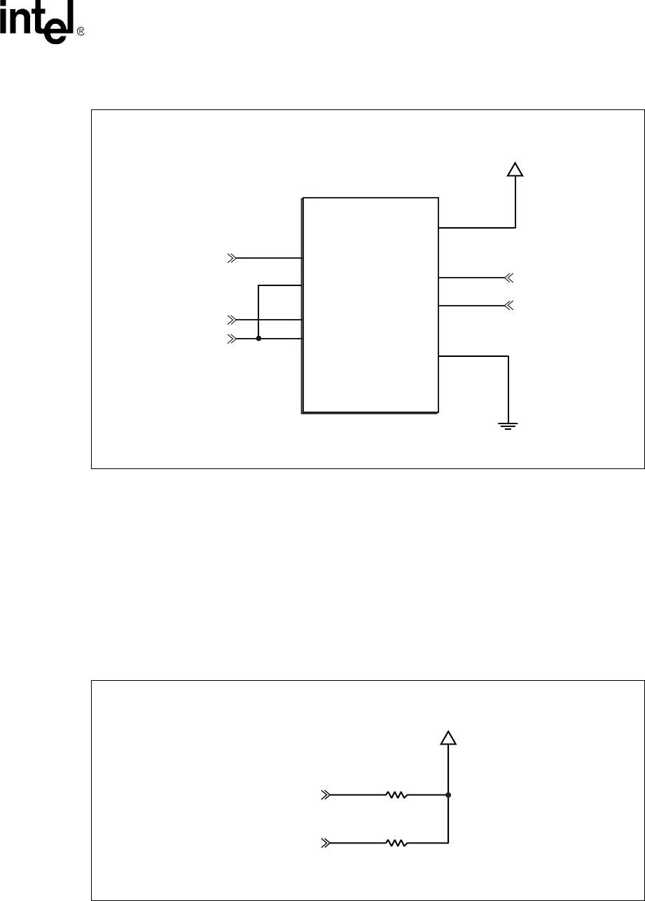
7.1.4 Pull-Ups and Pull-Downs
The I
2
C Bus Specification, available from Philips Corporation, states:
The external pull-up devices connected to the bus lines must be adapted to accommodate the shorter
maximum permissible rise time for the Fast-mode
I
2
C-bus. For bus loads up to 200 pF, the pull-up
device for each bus line can be a resistor; for bus loads between 200 pF and 400 pF, the pull-up device
can be a current source (3 mA max.) or a switched resistor circuit.
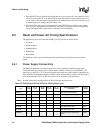
The design presented in this guide is not intended for loads larger than 200pF, so the pull-up device is a
resistor as shown in Figure 7-3.
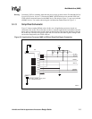
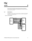
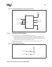
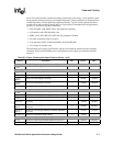
Figure 7-2. Using an Analog Switch to Allow a Second CF Card
A8750-01
CI_I2C_SDA
DC3P3V
MAX4547
U26
AAAF
CF_I2C_SCL
SA_I2C_SCL
V*
NC_1
COM_1
IN_7
NC_2
GND
1
5
6
2
8
7
SA_I2C_SDA
COM_7
4
SA_I2C_ENAB
IN_2
3
Figure 7-3. I
2
C Pull-Ups and Pull-Downs
A8751-01
DC3P3V
R5
4.99K
SA_I2C_SDA
R4
4.99K
SA_I2C_SCL