


PXA250 and PXA210 Applications Processors Design Guide 5-1
MultiMediaCard (MMC) 5
The MultiMediaCard (MMC) is a low cost data storage and communication media. The MMC
supports the translation protocol from a standard MMC or Serial Peripheral Interface (SPI) bus to
an application bus.
The MMC controller in the applications processor is compliant with The MultiMediaCard System
Specification, Version 2.1. The only exception is one and three byte data transfers are not
supported. The MMC controller is capable of communicating with a card in MMC or SPI mode.
Your application is responsible for specifying the MMC controller communication mode.
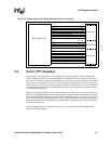
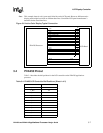
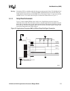
5.1 Schematics
The MultiMediaCard (MMC) controller on the applications processor supports MMC and SDCard
devices. (The MMC controller does not support SDCard nibble mode.) This section presents
several options on how to connect each type of device to the controller.
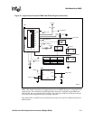
5.1.1 Signal Description
MMC controller signal functions are described in Table 5-1.
The MMCLK, MMCCS0, and MMCCS1 signals are routed through alternate functions within the
applications processor general purpose input/output (GPIO) module. Each of these signals can be
programmed to a particular GPIO pin.
The signals defined in The MultiMediaCard System Specification for an MMC device are CLK,
CMD, and DAT which correspond to the MMCLK, MMCMD, and MMDAT in the applications
processor, respectively. The two chip selects in the controller are for the MMC SPI mode and
correspond to the reserved pin of two different devices, defined in the specification.
The signals defined in the Physical Layer Specification of the SD Memory Card Specifications for
an SDCard device are CLK, CMD, and DAT0-DAT3. The obvious difference is the number of
DAT signals. In addition, the socket for an SDCard contains mechanical switches for write protect
(WP) and card detect (CD). For an SDCard to be connected to the MMC controller, only one data
line, DAT0, is used. Otherwise the signal mapping remains the same as an MMC device. The WP
and CD switches on the socket are discussed in Section 5.1.2, “How to Wire” on page 5-2.
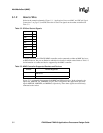
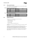
Table 5-1. MMC Signal Description
Signal Name Input/Output Description
MMCLK Output Clock signal to MMC
MMCMD BiDirectional Command line
MMDAT BiDirectional Data line
MMCCS0 Output Chip Select 0
MMCCS1 Output Chip Select 1