


vi PXA250 and PXA210 Applications Processors Design Guide
Contents
Figures
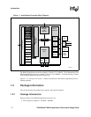
1-1 Applications Processor Block Diagram......................................................................................1-2
1-2 PXA250 Applications Processor..............................................................................................1-11
1-3 PXA210 Applications Processor..............................................................................................1-15
2-1 General Memory Interface Configuration ..................................................................................2-2
2-2 SDRAM Memory System Example............................................................................................2-4
2-3 32-Bit Variable Latency I/O Read Timing (Burst-of-Four, One Wait Cycle Per Beat)..............2-10
2-4 Expansion Card External Logic for a Two-Socket Configuration.............................................2-12
2-5 Expansion Card External Logic for a One-Socket Configuration.............................................2-13
2-6 Alternate Bus Master Mode .....................................................................................................2-15
2-7 Variable Latency I/O ................................................................................................................2-16
2-8 CS, CKE, DQM, CLK, MA minimum loading topology.............................................................2-17
2-9 CS, CKE, DQM, CLK, MA Maximum Loading Topology .........................................................2-17
2-10MD Minimum Loading Topology..............................................................................................2-17
2-11MD maximum loading topology ...............................................................................................2-18
3-1 Single Panel Monochrome Passive Display Typical Connection ..............................................3-3
3-2 Passive Monochrome Single Panel Displays, Double-Pixel Data Typical Connection..............3-3
3-3 Passive Monochrome Dual Panel Displays Typical Connection ...............................................3-4
3-4 Passive Color Single Panel Displays Typical Connection .........................................................3-4
3-5 Passive Color Dual Panel Displays Typical Connection............................................................3-5
3-6 Active Color Display Typical Connection...................................................................................3-7
4-1 Self Powered Device .................................................................................................................4-1
5-1 Applications Processor MMC and SDCard Signal Connections................................................5-3
5-2 Applications Processor MMC to SDCard Simplified Signal Connection....................................5-5
6-1 AC97 connection .......................................................................................................................6-1
7-1 Linear Technology DAC with I2C Interface ...............................................................................7-2
7-2 Using an Analog Switch to Allow a Second CF Card ................................................................7-3
7-3 I
2
C Pull-Ups and Pull-Downs.....................................................................................................7-3
8-1 Power-On Reset Timing ..........................................................................................................8-12
8-2 Hardware Reset Timing...........................................................................................................8-13
8-3 GPIO Reset Timing .................................................................................................................8-13
8-4 Sleep Mode Timing..................................................................................................................8-14
8-5 Example Form Factor Reference Design Power System Design............................................8-22
9-1 JTAG/Debug Port Wiring Diagram ............................................................................................9-1
Tables
1-1 Revision History.........................................................................................................................1-1
1-2 Related Documentation .............................................................................................................1-1
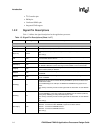
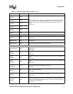
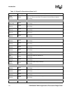
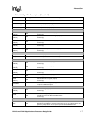
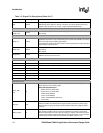
1-3 Signal Pin Descriptions..............................................................................................................1-4
1-4 PXA250 Applications Processor Pinout — Ballpad Number Order .........................................1-12
1-5 PXA210 Applications Processor Pinout — Ballpad Number Order .........................................1-16
2-1 Memory Address Map ...............................................................................................................2-3
2-2 SDRAM Memory Types Supported by the Applications Processor...........................................2-5
2-3 Normal Mode Memory Address Mapping ..................................................................................2-6
2-4 Applications Processor Compatibility Mode Address Line Mapping..........................................2-7
2-5 Valid Booting Configurations Based on Package Type .............................................................2-8
2-6 BOOT_SEL Definitions..............................................................................................................2-8