


PXA250 and PXA210 Applications Processors Design Guide 5-3
MultiMediaCard (MMC)
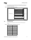
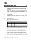
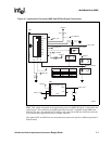
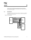
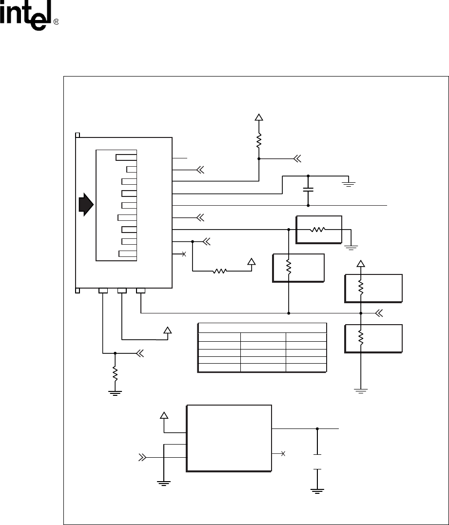
MMC_CS0, which corresponds to the applications processor MMCCS0 signal, is connected to the
socket at pin 1. This connection is the SPI mode chip select and is available on both MMC and
SDCard. This pin is also labeled DAT3. DAT3 is only used with an SDCard in SDCard mode and
not available on the applications processor MMC controller.
The signals DAT1 and DAT2 are not connected because these are specific to SDCard operation in
SDCard mode.
Figure 5-1. Applications Processor MMC and SDCard Signal Connections
A8698-01
WP
CHECK II
COMM
CD
12
11
10
DAT2
MMC_C50
SA_MMCCLK
0
10K
0.1uF
DC3P3V
R147
J10
U27
C91
Bottom Mount
CD_DAT3
CMD
VSS1
VDD
CLK
VSS2
DAT0
DAT1
VIN
GND
EN
VOUT
BYP
8
7
1
2
3
4
5
6
SA_MMDAT
MMC_PWR
SA_MMCMD
MMC_WP
MMC_ON
MMC_PWR
0K
R225
47.5K
R150
0K
R226
DNI IF MMC
DNI
IF
SD
DC3P3V
DC5P5V
DC3P3V
DC3P3V
nMMC_DETECT
100K
R227
DNI
IF
SD
100K
R228
100K
R229
C92
4.7uF
DNI
IF
MMC
MIC5207- 3.38M5
3.3V LDO REG 180ns
LE33
4
5
12
1
2
3
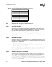
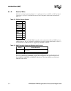
CARD Selection Resistors and Values
Resistors SDCard MMC
R226
R227
R225
R228
DNI
DNI
0
100K
0
100K
DNI
DNI