


PXA250 and PXA210 Applications Processors Design Guide 4-1
USB Interface 4
4.1 Self Powered Device
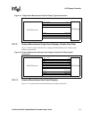
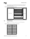
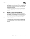
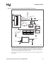
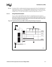
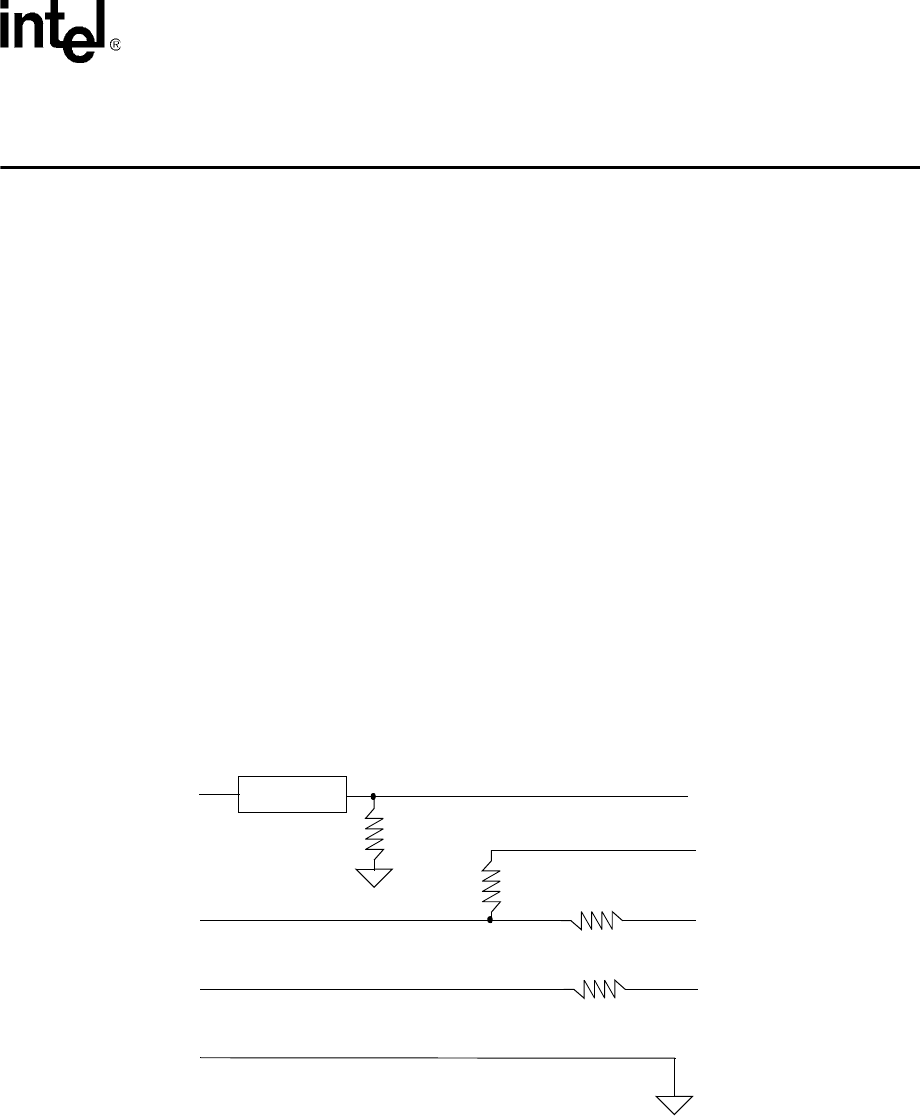
Figure 4-1 shows the USB interface connection for a self-powered device. The 0 ohm resistors are
optional, and if not used, then connect USB UDC+ directly to the device UDC+ and connect USB
UDC- directly to device UDC-. The device UDC+ and UDC- pins match the impedance of a USB
cable, 90 ohms, without the use of external series resistors. You may install 0 ohm resistors on your
board to compensate for minor differences between the USB cable and your board trace
impedance.
The 5 to 3.3 voltage divider is required since the device GPIO pins cannot exceed 3.3 V. This
voltage divider can be implemented in a number of ways. The most robust and expensive solution
is to use a MAX6348 Power-On-Reset device. This solution produces a very clean signal edge and
minimizes signal bounce. The more inexpensive solution is to use a 3.3 V line buffer with 5 V
tolerant inputs. This solution does not reduce signal bounce, so software must compensate by
reading the GPIO signal after it stabilizes. A third solution is to implement a signal bounce
minimization circuit that is 5 V tolerant, but produces a 3.3 V signal to the GPIO pin.
Note: If GPIOn and GPIOx are the same pin, never put the device to sleep while the USB cable is
connected to the device. During sleep, the USB controller is in reset and will not respond to the
host; after sleep, the device will not respond to its host-assigned address.
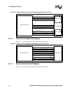
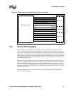
Figure 4-1. Self Powered Device
4.1.1 Operation if GPIOn and GPIOx are Different Pins
Any GPIO pins can be defined as GPIOn and GPIOx. GPIOn should be a GPIO which can bring
the device out of sleep. Out of reset, configure GPIOx as an input that causes the UDC+ line to
float. GPIOn is configured as an input that causes an interrupt whenever a rising or falling edge is
USB 5V
USB UDC+
USB UDC-
USB GND
5V to 3.3V
1.5K
GPIOn
UDC+
UDC-
0 ohm
(optional)
0 ohm
(optional)
Board GND
470K
GPIOx