


2-14 PXA250 and PXA210 Applications Processors Design Guide
System Memory Interface
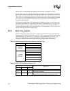
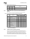
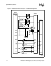
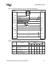
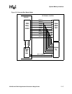
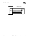
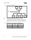
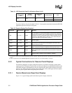
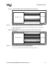
2.6.6 DMA / Companion Chip Interface
Connect a companion chip to the applications processor via:
• Alternate Bus Master Mode
• Variable Latency I/O
• Flow through DMA
These connections are illustrated in Figure 2-6 and Figure 2-7.
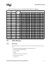
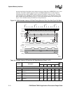
tcardDH
MD(31:0) hold after nPWE, nPOE,
nPIOW, or NPIOR de-asserted
10 8.5 7.5 6.8 6 ns, 1
tcardCMD
nPWE, nPOE, nPIOW, or nPIOR
command assertion
30 25.5 22.5 20.4 18 ns, 1
NOTE:
1. These numbers are minmums. They can be much larger based on the programmable Card Interface
timing registers.
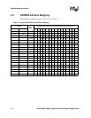
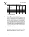
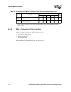
Table 2-9. Card Interface (PCMCIA or Compact Flash) AC Specifications (Sheet 2 of 2)
Symbol Description
MEMCKLK
Units
Notes
99.5 118.0 132.7 147.5 165.9