


PXA250 and PXA210 Applications Processor Design Guide 3-5
LCD Display Controller
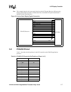
3.3 Active (TFT) Displays
Because data is sent to the panel as raw 16-bit pixel data, active displays require16 data pins in
order to transfer the pixel data from the controller. All 16 data lines are also required to drive one
pixel value. The 16 bits of data describe the intensity level of the red, green and blue for each pixel.
Typically, this is formatted as 5 bits for red, 6 bits for green and 5 bits for blue, but this can vary by
display and is controlled by the software writing to the frame buffer. Refer to the display datasheet
to ensure that the correct the PXA250 applications processor LCD data lines are connected to the
correct LCD panel data lines.
Many active displays actually have more than 16 data lines - usually 18 (6 of each color). For these
panels it is recommended that the most significant lines of the panel lines are connected to the data
lines from the PXA250 applications processor. This maintains the panel’s full range of colors but
increases the granularity of the color spectrum with an insufficient number of data lines. All unused
panel data lines can be tied either high or low. Other options include tying the LSB of red and blue
to the next bit, R1 or B1.
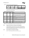
For active displays, connect the pins described in Table 3-3 between the PXA250 applications
processor and the LCD panel.
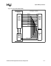
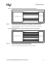
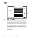
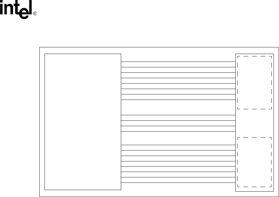
Figure 3-5. Passive Color Dual Panel Displays Typical Connection
PXA250 Processor
LCD Display
L_DD0
L_DD1
L_DD2
L_DD3
L_DD4
L_DD5 - Top left Blue for upper panel
L_DD6 - Top left Green for upper panel
L_DD7 - Top left Red for upper panel
L_PCLK
L_LCLK
L_FCLK
L_BIAS
Upper Panel
Lower Panel
L_DD8
L_DD9
L_DD10
L_DD11
L_DD12
L_DD13 - Top left Blue for lower panel
L_DD14 - Top left Green for lower panel
L_DD15 - Top left Red for lower panel
Pixel_Clock
Line_Clock
Frame_Clock
Bias
DU_0
DU_1
DU_2
DU_4
DU_5
DU_6
DU_7
DU_3
DL_0
DL_1
DL_2
DL_4
DL_5
DL_6
DL_7
DL_3