


PXA250 and PXA210 Applications Processor Design Guide 3-1
LCD Display Controller 3
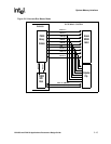
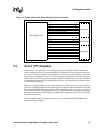
This chapter describes sample hardware connections from the PXA250 applications processor to
various types of LCD controllers. Active (TFT) as well as passive (DSTN) displays are discussed
as well as single and dual panel displays. These should not be considered the only possible ways to
connect an LCD panel to the PXA250 applications processor, but should serve as a reference to
assist with hardware design considerations. Other panels, for example panels without L_FCLK or
L_LCLK, have been successfully connected to the PXA250.
3.1 LCD Display Overview
The PXA250 applications processor supports both active and passive LCD displays. Active
displays generally produce better looking images, but at a higher cost. Passive displays are
generally less expensive, but their displays are inferior to active displays. However, recent
advances in dithering technology are closing the quality gap between passive and active displays.
Note: Names used for “LCD Panel Pin” are representative names and may not match those on all LCD
panels. Refer to the LCD panel reference documentation for the actual name.
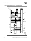
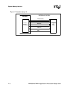
3.2 Passive (DSTN) Displays
Several different types of passive displays are available in both color and monochrome. These
maybe single or dual panel displays. Additionally, some monochrome displays use double-pixel
data mode (twice the number of pixels as a normal monochrome display). With the exception of the
number of data pins required, all of these choices affect the software configuration and support, not
the system hardware design. In fact, most passive displays use a single interconnection scheme. For
information on the software changes and performance considerations of the various display
options, refer to the PXA250 and PXA210 Applications Processors Developer’s Manual.
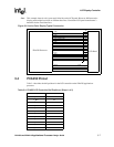
Passive displays drive dithered data to the LCD panel - which means that for each pixel clock cycle
a single data line drives an ON/OFF signal for one color of a single pixel.
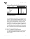
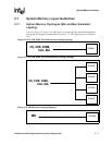
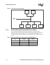
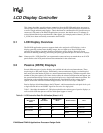
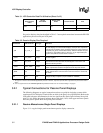
Table 3-1 describes the number of L_DD pins required for the various types of passive displays, as
well as which LCD data pins are used for which panel (upper or lower).
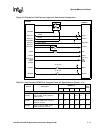
Table 3-1. LCD Controller Data Pin Utilization (Sheet 1 of 2)
Color/
Monochrome
Panel
Single/
Dual Panel
Double-Pixel
Mode
Screen Portion Pins
Monochrome Single No Whole L_DD<3:0>
Monochrome Single Yes Whole L_DD<7:0>
1
Monochrome Dual No
Top L_DD<3:0>
Bottom L_DD<7:4>
Color Single N/A Whole L_DD<7:0>