


5-2 PXA250 and PXA210 Applications Processors Design Guide
MultiMediaCard (MMC)
5.1.2 How to Wire
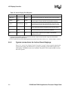
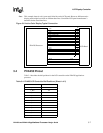
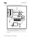
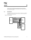
Notice in the example schematic (Figure 5-1, “Applications Processor MMC and SDCard Signal
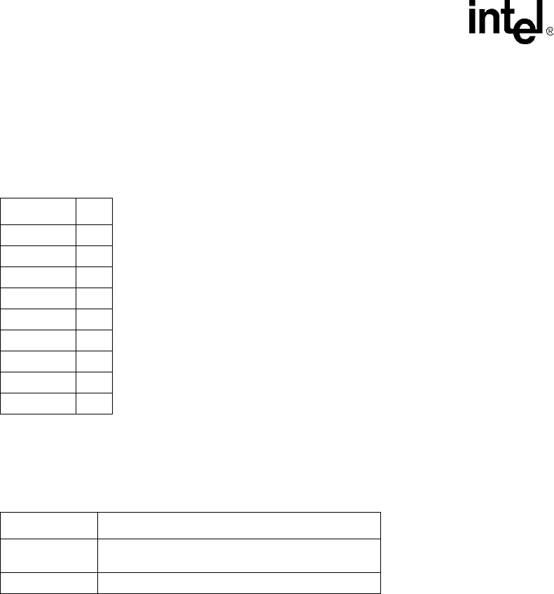
Connections” on page 5-3) an SDCard socket is used. The signals on the socket are defined in
Table 5-2.
As stated previously, the PXA250 MMC controller can be connected to either an MMC device or
an SDCard device, but you are limited to which device installs in which socket. Refer to Table 5-3
for information on sockets and device supported by the MMC controller.
Figure 5-1 is a schematic that supports both MMC and SDCard devices. In the schematic, the
signals SA_MMCLK, SA_MMCMD, and SA_DAT correspond to the applications processor
signals MMCLK, MMCMD, and MMDAT, respectively. These three signals are also directly
connected to the socket.
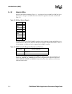
Table 5-2. SDCard Socket Signals
Signal Name Pin #
DAT3 1
CMD 2
VSS1 3
VDD 4
CLK 5
VSS2 6
DAT0 7
DAT1 8
DAT2 9
Table 5-3. MMC Controller Supported Sockets and Devices
Sockets Devices Supported
SDCard socket
SDCard device
MMC device
MMC socket MMC device