


6-2 PXA250 and PXA210 Applications Processors Design Guide
AC97
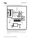
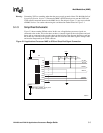
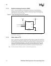
6.2 Layout
Because of the analog/digital nature of the codecs, it is important that proper mixed-signal layout
procedures be followed. Intel recommends you follow the layout recommendations given in your
Codec datasheet. Some general recommendations are:
• Use a separate power supply for the analog audio portion of the design.
• Place a digital power/ground plane keep-out underneath the analog portion. Use a separate
analog ground plane. You can create an island inside the keep-out. Connect the digital ground
pins of the codec to the digital ground. Keep the two ground planes on the same layer, with at
least 1/8 of an inch separation between them.
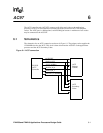
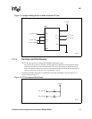
• Connect the two ground planes underneath your codec with a 0 ohm jumper. Add optional Do
Not Populate 0 ohm jumpers between analog and digital ground at the power supply.
Excessive noise on the board may be reduced by installing the 0 ohm resistor.
• Do not to route digital signals underneath the analog portion. Digital traces must go over the
digital ground plane, analog traces over the analog plane.
• Buffer any digital signals to or from the codec that go off the board, for example, if your codec
is on a daughter card.
• Fill the areas between analog traces with copper tied to the analog ground. Fill the regions
between digital traces with copper tied to the digital ground.
• Locate the decoupling capacitors for the analog portion as close to the codec as possible.