


PXA250 and PXA210 Applications Processor Design Guide 3-9
LCD Display Controller
However, typical transfer rates are considerably less than 83 Mhz. For example, an 800x600 color
active display running at 75 Hz requires a transfer rate of approximately 36 MHz. To determined
this, calculate the number of pixels (800 x 600 = 480,000) and multiply by the screen refresh rate
(75 Hz). Since active panels replace 1 pixel of data with every clock cycle this determines the final
transfer rate. Active displays normally do not require refresh rates as high as 75 Hz, so you may use
a lower refresh rate to reduce transmission rates even more.
Passive displays often do require refresh rates greater than 75 Hz, which transfers more pixels each
clock cycle. For instance, a color passive display with 8 data lines transfers 2 2/3 pixels’ worth of
data each clock cycle. This divides the transmission rate by 2 2/3. Further reductions in the transfer
rate come by using dual panel displays which use twice as many data lines to transfer data - halving
the rate again.
Generally, this gives you lower transfer rates to even large displays and thus simpler design
considerations and fewer layout constraints.
When laying out your design, minimize trace length of the LCD panel signals and allow sufficient
spacing between signals to avoid crosstalk. Crosstalk decreases the signal integrity, especially the
data line signals.
LCD system design is not considered to be critical as infrequent or single bit errors are, typically,
not noticed by the user. Also, the errors are transitory, as the old data is constantly being replaced
with new data. Slower panel refresh rates increase the likelihood that a single error is noticed by the
user. However, there is an counteracting effect in that slower refresh rates relax LCD timing and
therefore result in fewer screen transmission errors. There are other factors related to choosing a
refresh rate for an LCD system, most significant is the impact on system bandwidth.
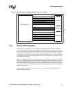
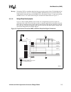
If you must use excessively long or poorly routed signals, one possible solution is to add buffers
between the PXA250 applications processor and the LCD panel. This helps strengthen the LCD
panel signal levels and synchronizes signal timing. However, this is usually not required as the
LCD panel timings are fairly relaxed. Since the LCD display essentially operates asynchronously
from the processor, the propagation delay of the buffers is not a major concern.
When mounting the LCD panel, it is critical to shield the touchscreen control lines, if present.
Noise from the LCD panel and its control signals can become injected into the touchscreen control
lines, causing spurious touch interrupts or loss of resolution.
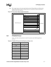
3.5.4 Panel Connector
Most LCD panels are connected to the system board via a connector, instead of being directly
mounted on the system board. This increases flexibility and ease of manufacture. Typically the
manufacturer of the panel recommends a particular connector for the panel. Follow the panel
manufacturer’s recommendation.