


5-4 PXA250 and PXA210 Applications Processors Design Guide
MultiMediaCard (MMC)
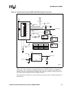
Three other signals shown on the connector are COMM and the mechanical switches write protect
(WP) and card detect (CD). WP and CD are both connected to COMM via a mechanical switch
inside the socket when a device is inserted.
Three other signals shown on the connector are COMM and the mechanical switches WP and CD.
When a device is inserted in the example schematic (Figure 5-1), WP may be and CD is connected
to COMM via a mechanical switch inside the socket
SDCard devices have a write protect tab. Depending on the position of the tab, the WP signal may
or may not be connected to the COMM signal. Connect the WP signal to a CPLD or other device
capable of indicating to the driver software that the card is write protected. In this example,
COMM is tied to a VCC and WP has a pull-down resistor. This causes a rising edge when the tab is
in the write protect position and the WP signal remains low when the tab is in the read/write
position.
The CD signal, MMC_DETECT, indicates to the MMC controller when a card is installed. It is
used for both an SDCard socket and an MMC socket. Since the MMC socket does not have the
mechanical CD switch, other measures must be taken to produce a card detect. Thus, the SDCard
and MMC cases are discussed separately.
Note: While this schematic shows two ways to create a card detect, it is recommended that an SDCard
socket be used if a card detect and write protection signal are desired even if only MMC devices
are being used.
5.1.2.1 SDCard Socket
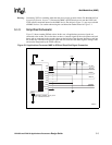
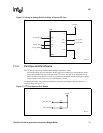
When using Figure 5-1, “Applications Processor MMC and SDCard Signal Connections” on
page 5-3 as a template for your SDCard circuit design, all resistors labeled “DNI IF SD” should not
be installed and all resistors labeled “DNI IF MMC” should be installed in the circuit. Removing
R226 and inserting R225 causes the VSS2 signal on pin 6 to be tied to ground. Also, the SDCard
needs a pull-down resistor in position R228.
SDCard sockets have a card detect switch internal to the socket. The CD signal is physically
connected to the COMM signal. Connect the CD signal to a CPLD or other device capable of
indicating to the driver software that a card has been inserted in the socket. In this example,
COMM is tied to a V
CC
and CD has a pull-down resistor. This causes a rising edge on CD when a
card is inserted while the CD signal remains low if no card is in the socket.
5.1.2.2 MMC Socket
When using Figure 5-1, “Applications Processor MMC and SDCard Signal Connections” on
page 5-3 as a template for your MMC circuit design, all resistors labeled “DNI IF MMC” should
not be installed and all resistors labeled “DNI IF SD” should be installed in the circuit. This causes
the VSS2 signal on pin 6 to be pulled-up through resistor R227.
Unlike SDCard sockets, MMC sockets do not have a card detect or write protect switch. In order to
implement this, a pull-up is placed on the VSS2 signal (pin 6 of the socket.) Since VSS2 and VSS1
are connected internally on the MMC device, the signal called nMMC_DETECT on the schematic
is driven low when the MMC device is inserted.