


2-18 PXA250 and PXA210 Applications Processors Design Guide
System Memory Interface
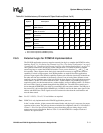
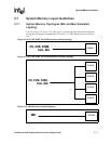
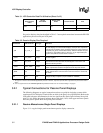
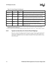
2.7.2 System Memory Recommended Trace Lengths
Table 2-10 details the minimum and maximum trace lengths that were simulated for the
applications processor. These trace lengths are not the absolute trace lengths that will work given
the loading conditions. The trace lengths in Table 2-10 are measured from the applications
processor to the individual component pins. The board impedance for the simulations was 60ohm
+/- 10%.
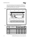
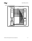
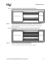
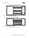
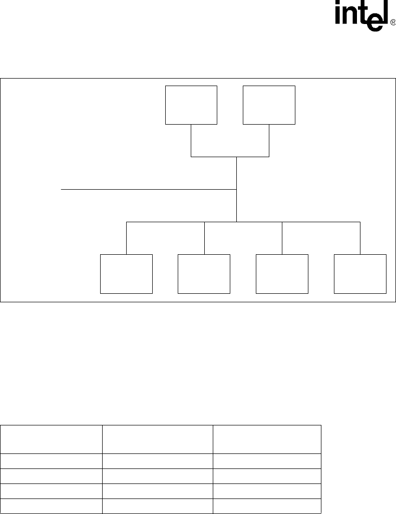
Figure 2-11. MD maximum loading topology
MD
SDRAM SDRAM
AUXAUXAUXAUX
Table 2-10. Minimum and Maximum Trace Lengths for the SDRAM Signals
Signal
Min
Trace Length
Max
Trace Length
CS, CKE, DQM 0.75 in 4.5 in
CLK 1.0 in 4.25 in
MA 1.0 in 4.5 in
MD 1.0 in 4.25 in