


Reelmaster 5010 Series Hydraulic System (Rev. C)Page 4 -- 67
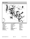
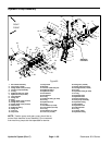
Removal (Fig. 58)
1. Parkthe machineona levelsurface, engageparking
brake, lower cutting units and stopengine. Remove key
from the ignition switch.
2. Remove two (2) flange head screws and flange nuts
that secure drive shaft guard hoop to machine frame.
Remove guard.
3. Remove two (2) cap screws (item 5) and flange nuts
(item9)thatsecuredriveshaftyoke topistonpumpinput
shaft.
4. Removesix (6) capscrews (item7) that securedrive
shaft flange to engine flywheel.
5. Remove drive shaft assembly from machine.
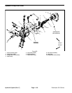
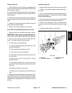
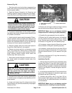
Drive Shaft Cross and Bearing Service (Fig. 59)
1. Remove snap rings that secure bearings in yokes.
IMPORTANT: Yokes must be supported when re-
moving and installing bearings to prevent damage.
2. Use a press to remove cross and bearings from
yokes. Thoroughly clean drive shaft yokes.
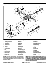
3. To install new cross and bearings:
A. Apply a coating ofgrease to bearing bores in end
yoke and shaft yoke.
B. Press one bearing partially into yoke.
C. Insert cross into yoke and bearing.
D. Holdcross inalignment and pressbearing inuntil
it hits the yoke.
E. Install snap ring into yoke groove to s ecure
installed bearing.
F. Place second bearing into yoke bore and onto
cross shaft. Press bearing into yoke and secure with
snap ring.
G. Repeat procedure for other yoke.
H. Greasecrossuntilgreasecomesoutofallfour(4)
cups.
4. Make sure that assembled joint moves without bind-
ing. Slight binding can usually be eliminated by lightly
rapping the yoke lugs with a soft faced hammer. If bind-
ing continues, disassemble joint to identify source of
binding.
Installation (Fig. 58)
1. Applyantiseizelubricanttotractionpumpinputshaft.
2. Positiondriveshaftassembly toengineandpumpin-
put shaft.
3. Secure drive shaft flange to engine flywheel with six
(6) cap screws (item 7). Torque cap screws from 34 to
42 ft--lb (46 to 56 N--m).
4. Secure drive shaft yoke to pump input shaft w ith two
(2) cap screws (item 5) and flange nuts (item 9).
5. Position drive shaft guard hoop to machine frame
and secure with two ( 2) flange head screws and flange
nuts.
6. Lubricate grease fittings on drive shaft.
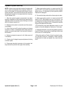
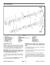
1. End yoke
2. Cross and bearing kit
3. Snap ring (4 used)
4. Shaft yoke
Figure 59
1
2
3
4
3
Hydraulic
System