


Reelmaster 5010 Series Page 6 -- 17 Chassis (Rev. C)
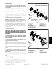
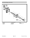
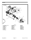
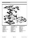
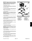
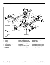
Axle Pivot Bushings (Fig. 11)
The r ear axle must be held in place snugly by the axle
pivot pin. Excessive movement of the axle, which is
characterized by erratic steering, might indicate worn
axle pivot bushings. To correct the problem, replace the
bushings (item 36).
1. Remove rear axle from machine (see Rear Axle Re-
moval in this s ection).
2. Use a bushingremoval tool to extract bothaxle pivot
bushings fromthe axlepivot tube.Take care tonot dam-
age bore of pivot tube during bushing removal. Clean
theinside ofthetube toremovedirtand foreignmaterial.
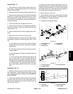
3. Apply grease to the inside and outside of the new
bushings.Use anarbor pressto installthe bushingsinto
the front and back of the axle pivot tube. Bushings must
be flush with the axle tube.
4. Install rear axle to machine (see Rear Axle Installa-
tion in this section).
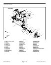
Rear Axle Spindle Bushings (Fig. 11)
The r ear wheel spindles must fit snugly in the rear axle.
Excessive movement of the spindle in the axle mightin-
dicate that the spindle bushings (item 43) are worn and
must be replaced.
1. Remove rear axle from machine (see Rear Axle Re-
moval in this s ection).
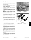
2. Remove cotter pin and slotted hex nut that secure
the tie rod end to the drag link. Separate the tie rod end
from the drag link.
3. If right side spindle is being removed, remove cotter
pin and slottedhex nut that secure steering cylinderball
joint to drag link. Separate steering cylinder from drag
link.
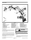
4. Remove the flange head screw, spindle cap and re-
taining ring that secure the wheel spindle into the axle
tube. Slide the spindle and wheel assembly out of the
axletubetoexposethespindlebushings.Locateandre-
trieve thrust washer (item 19) from wheel spindle shaft.
5. Use a bushing removal tool to extract both bushings
from the axle tube. Take care to not damage the bore of
theaxletube.Cleanthe insideoftheaxle tubetoremove
any dirt or foreign material.
6. Apply grease to the inside and outside of the new
bushings.Use anarbor pressto installthe bushingsinto
the top and bottom ofthe axle tube. Press bushings into
tube until flange shoulder bottoms on tube.
7. Thoroughly clean the spindle shaft. Inspect the
spindle for wear and replace if worn or damaged.
8. Install thrust washer (item 19) onto the spindle shaft
and slide the shaft up through the axle tube. Hold the
wheelandspindleshaftassemblyinplaceandinstallthe
retaining ring (item13) onto the end ofthe spindle shaft.
9. Install the spindle cap and flange head screw.
10.Connect the tie rod end to the drag link with slotted
hex nut and cotter pin.
11.If separated, secure steering cylinder ball joint to
drag link with slotted hex nut and cotter pin.
12.Install rear axle to machine (see Rear Axle Installa-
tion in this section).
13.Lubricate the steering spindles through the grease
fittings on the rear axle.
14.Check rear wheel toe--in (see Traction Unit Opera-
tor’s Manual).
15.After all adjustments have been made, make sure
that no contact is made between any machine compon-
ents as the wheels are moved from lock to lock. Re-
adjust if necessary.
Chassis