


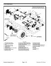

Reelmaster 5010 SeriesHydraulic System (Rev. C) Page 4 -- 74
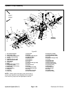
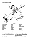
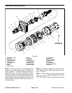
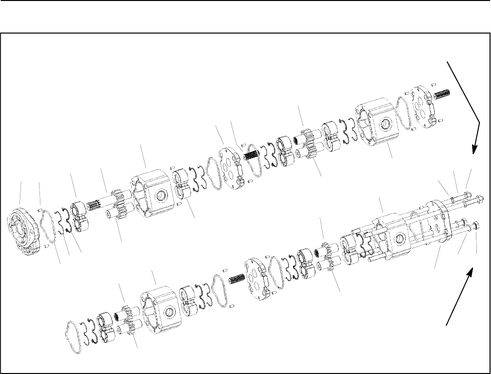
Gear Pump Service
1. Front cover
2. Dowel pin (16 used)
3. Square section seal (8 used)
4. Back--up ring (8 used)
5. Pressure seal (8 used)
6. Thrust plate (8 used)
7. Drive shaft
8. Driven gear (2 used)
9. Body
10. Flange (3 used)
11. Splined connecting shaft (3 used)
12. Drive gear
13. Body
14. Drive gear
15. Driven gear
16. Body
17. Drive gear
18. Driven gear
19. Body
20. Rear cover
21. Washer (4 used)
22. Stud bolt (2 used)
23. Nut (2 used)
24. Cap screw (2 used)
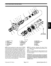
Figure 63
4
1
2
9
10
11
8
5
6
7
12
3
6
8
13
14
17
18
15
16
19
20
21
22
23
24
21
33 ft--lb
(45 N--m)
33 ft--lb
(45 N--m)
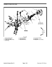
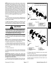
Disassembly (Fig. 63)
NOTE: Thegearpump mustbereplaced asacomplete
assembly. Individual gears, housings and thrust plates
are not available separately. Disassemble gear pump
for cleaning, inspection and seal replacement only.
IMPORTANT: Keep bodies, gears, flanges and
thrustplatesfor eachpumpsectiontogether;do not
mix parts between pump sections.
1. Plug pump ports and thoroughly clean exterior of
pump with cleaning solvent. Make sure work area is
clean.
2. Use a marker to make a diagonal line across the
gear pump for assembly purposes (Fig. 64).
IMPORTANT: Use caution when clamping gear
pump in avise toavoid distorting anypump compo-
nents.
3. Secure the front cover of the pump in a vise with the
drive shaft pointing down.
4. Loosen the two (2) cap screws and two (2) nuts that
secures pump assembly.
5. Remove pump from vise and remove fasteners.
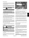
6. Supportthepumpassembly andgentlytapthepump
case with a soft face hammer to loosen the pump sec-
tions. Be careful to not drop parts or disengage gear
mesh.