


Reelmaster 5010 Series
Cutting Units (Rev. C)
Page 7 -- 23
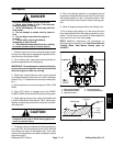
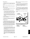
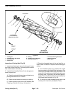
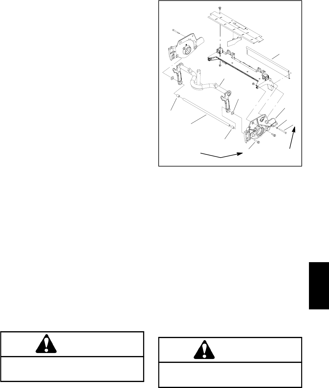
Reel Assembly Removal (Fig. 26)
1. Positionmachine on aclean andlevel surface,lower
cutting units,stop engine,engage parkingbrake andre-
move key from the ignition switch.
2. Remove the cutting unit from the machine and place
on a flat work area.
3. Ifcutting unitis equipped witha counterweighton LH
side plate (as shown in Figure 26), remove the two (2)
capscrewssecuringthecounterweighttothesideplate.
Remove counter weight from the cutting unit. Remove
and discard o--ring from counter weight.
4. Ifcutting unitis equippedwith anoptionalgroomer or
rear roller brush, remove components for those options
from left handside plate of cutting unit.See Service and
Repairs section of Chapter 8 -- Groomer for information
on groomer. See Rear Roller Brush in the Service and
Repairs section of this chapter for information on rear
roller brush.
5. Remove the bedbar pivot bolt and washers from the
LH side plate.
6. Loosenfasteners thatsecure frontand rearrollers to
LHsideplate(seeFrontRollerRemovalandRearRoller
Removal in this s ection).
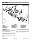
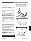
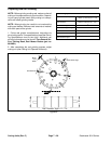
7. Remove cap screw and flat washer that secure rear
grass shield to LH side plate (Fig. 27).
8. Remove flange head screw that secures support
tube, frame spacer and carrier frame to LH side plate
(Fig. 27).
NOTE: Thereelbearings andgrease sealsare pressfit
on the cutting reel shaft and should remain on the reel
when removing the LH side plate.
NOTE: Side plates on 5” cutting reel attach to cutting
unit frame with two (2) shoulder bolts and flange nuts.
Sideplateson 7”cuttingreelusethree(3) shoulderbolts
and flange nuts.
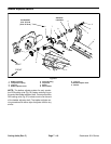
9. Removeshoulderbolts(item8)andflangenuts(item
24) that secure the LH side plate to the cutting unit
frame.RemovetheLH sideplatefromthereelshaft,roll-
ers, bedbar and cutting unit frame.
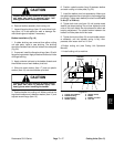
CAUTION
Contact with the reel, bedknife or other cutting
unit parts can result in personal injury. Use
heavy gloves when removing the cutting reel.
10.Carefully slide the cutting reel with bearings, grease
seals and splined inserts from the RH side plate.
11.Inspect and service cutting reel assembly as re-
quired (see Reel Assembly Service in this section).
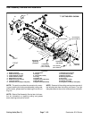
1. Carrier frame
2. Shim (if equipped)
3. Support tube
4. Frame spacer
5. Flat washer
6. Cap screw
7. Flange head screw
8. Rear grass shield
9. LH side plate
Figure 27
1
3
2
6
8
4
7
5
15 to 19 ft--lb
(20to25N--m)
27 to 33 ft--lb
(37to44N--m)
Loctite #242
9
4
Reel Assembly Installation (Fig. 26)
1. Thoroughly clean side plates and other cutting unit
components. Inspect side plates for wear or damage
and replace if needed.
NOTE: Check that grease seals on cutting reel shaft
are flush to 0.060” (1.5 mm) away from retaining ring on
reel shaft. If necessary, adjust position of grease seals
to allow proper clearance.
2. Make sure that grease seals and bearings are prop-
erly greased and positioned on cutting reel (see Reel
Assembly Service in this section). Apply thin coat of
grease to outside of grease seals and bearings on cut-
ting reel to ease reel installation. Also, apply grease to
bearing bores and threads in side plates.
CAUTION
Contact with the reel, bedknife or other cutting
unit parts can result in personal injury. Use
heavy gloves when installing the cutting reel.
Cutting
Units