


Rev. B
Reelmaster 5010 Series Hydraulic System (Rev. C)Page 4 -- 31
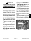
CAUTION
Before openinghydraulic system, operateall hy-
draulic controls to relieve system pressure and
avoid injury from pressurized hydraulic oil. See
Relieving HydraulicSystemPressure inthe Gen-
eral Information section of this chapter.
NOTE: Ifmachineisequipped withoptionalCrossTrax-
TM
AWD,reversereliefpressuretestports arelocatedon
CrossTrax
TM
hydraulic manifold.
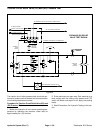
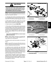
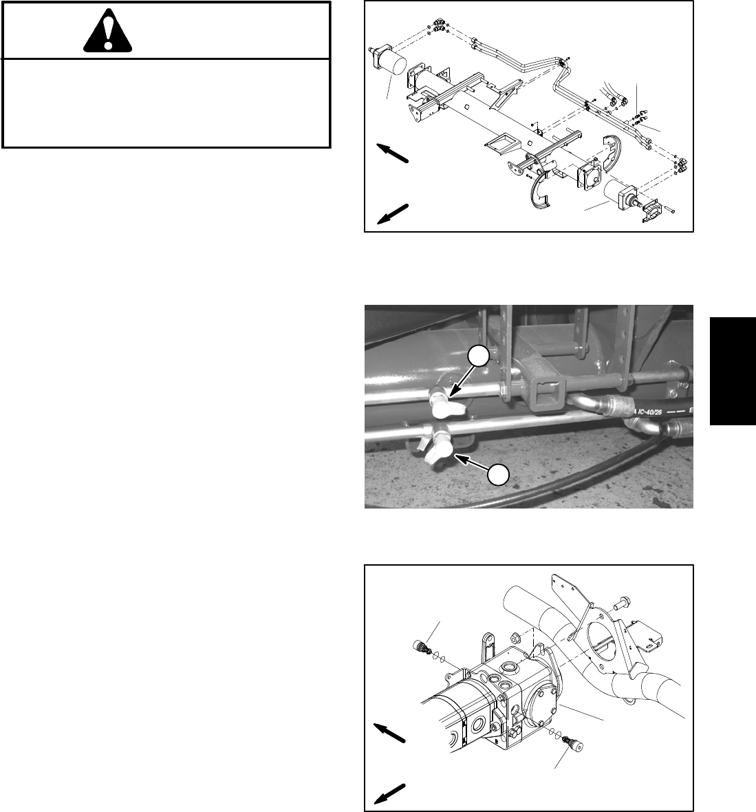
4. Thoroughly clean tractioncircuit test port onhydrau-
lictube fordirectiontobechecked(Fig. 25and26).Con-
nect a 5000 PSI (350 bar) pressure gauge to test port.
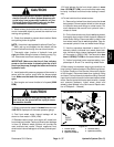
5. After installing tester, start engine and run at idle
speed. Check for any hydraulic leakage from test con-
nections and correct before proceeding with test.
6. Move throttle to full speed (3200 RPM).
7. Sit on seat, and with brakes applied, slowly depress
the traction pedal in the direction to be tested (forward
or reverse). While pushing traction pedaldown, careful-
ly watch the pressure gauge needle. As the traction re-
lief valve lifts, the gauge needle will momentarily stop.
Traction system pressure as the relief valve opens
should be:
Approximately3825 PSI(264bar)inbothf orward
(R3) and reverse (R4)
NOTE: If traction pedal continues to be pressed after
the relief valve has opened, system pressure can in-
crease higher than relief pressure.
8. Release traction pedal, stop engine and record test
results.
NOTE: Forward(R3) and reverse(R4) relief valvesare
identical. Relief valvescan beswitched intraction pump
to help in identifying a faulty relief valve.
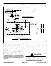
9. If problem occurs in one direction only, interchange
the relief valves in the traction pump (Fig. 27) to see if
the problem changes to the other direction. Clean or re-
place valves as necessary. These cartridge type valves
arefactoryset,andare notadjustable. Ifreliefvalvesare
in good condition, traction pump and/or wheel motors
should be suspected of wear and inefficiency.
10.After testing is completed, make sure that engine is
stopped and then relieve hydraulic system pressure
(See Relieving Hydraulic System Pressure in the Gen-
eral Information section of this chapter). Remove pres-
sure gauge from machine.
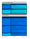
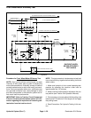
1. RH wheel motor
2. LH wheel motor
3. Forward test port
4. Reverse test port
Figure 25
2
3
4
1
FRONT
RIGHT
2WD MACHINE SHOWN
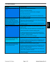
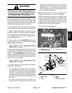
1. Forward test port 2. Reverse test port
Figure 26
1
2
2WD MACHINE SHOWN
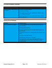
1. Piston (traction) pump
2. Reverse relief valve (R4)
3. Forward relief valve (R3)
Figure 27
2
3
1
FRONT
RIGHT
Hydraulic
System