


Reelmaster 5010 Series Page 6 -- 25 Chassis (Rev. C)
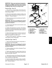
B. Pushdown andrearward onthe spring endto un-
hook the spring from the stop on the lift arm.
6. Disconnect hydraulic lift cylinder rod end clevis from
liftarm(seeLiftCylinderRemovalin theServiceandRe-
pairs section of Chapter 4 -- Hydraulic System). Pivotlift
cylinder rod end away from lift arm.
7. Remove lynch pin (item 12) and thrust washer (item
13) from rear of pivot yoke. Slide pivot yoke assembly
from lift arm. Locate and retrieve front thrust washer
(item 13).
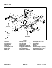
8. Remove two (2)flange head screws (item 6) thatse-
curespring catchtomachine. Removespringcatch, tor-
sion springs (items 23 and 24), two (2) spacers (item 1)
and two (2) washers (item 25).
9. Remove washer head screw that secures pivot pin
to frame.
10.Support rear lift arm to prevent it from falling. Slide
pivot pin from frame and lift arm. Remove rear lift arm.
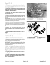
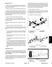
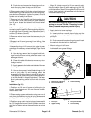
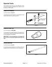
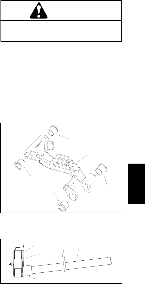
11.Inspect bushings in lift arm and pivot yoke for wear
ordamage.Ifnecessary,replacebushings(Figs.22and
23).
A. Use bushing removal tool to extract both bush-
ings from the lift arm or pivot yoke. Take care to not
damage the bore.
B. Clean the inside of the bore to remove any dirt or
foreign material.
C. Apply greaseto the inside andoutside of the new
bushings.
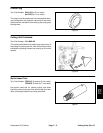
D. Use an arbor press to install the bushings into lift
arm or pivot yoke. Lift arm bushings should be
pressed until bushing flange is against lift arm bore.
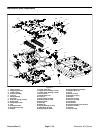
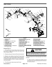
The upperpivot yoke bushingshould bepressed ful-
ly to the shoulder in the pivot yoke bore. The lower
pivot yoke bushing should be flush with the yoke
tube.
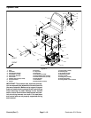
Installation (Fig. 21)
1. Position rear lift arm to frame and slide pivot pin
through frame bosses and lift arm. Secure pin with
washer head screw.
2. Place washer, spacer and torsion spring over rear of
each pivot pin. Position long leg of spring forward and
pointing out from top of spring.
3. Position spring catch to pivot pins and secure with
two (2) flange head screws (item 6). Make sure that
short end of torsion springs are against stop on spring
catch.
4. Align lift cylinder rod end to lift arm mounting slot.
Slide cylinder pin (item 30) with retaining ring (item 32)
and thrust washer (item 31) through the lift cylinder and
lift arm. Install second thrust washer on pin and secure
with second retaining ring.
CAUTION
Be careful when applying tension to the torsion
spring on the rear lift arms. The spring is under
heavy load and may cause personal injury.
5. Apply tension to torsion springs.
A. Insert nut driver or small piece of pipe onto the
long legofthe torsionspring onthe rearof thelift arm
pivot pin.
B. Pushdown andforwardonthe springendtohook
the spring to the stop bolt on the lift arm.
6. Mount cutting unit to lift arm.
7. Lubricate lift arm grease fittings.
1. Rear lift arm (LH shown)
2. Pivot yoke bushing
3. Lift arm bushing
Figure 22
2
1
3
2
3
1. Pivot yoke
2. Upper bushing
3. Pivot yoke shoulder
4. Lower bushing
Figure 23
1
2
3
4
Chassis