


Reelmaster 5010 SeriesGroomer Page 8 -- 8
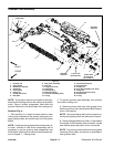
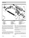
2. Install groomer plate assembly to groomer non--
drive side of cutting unit:
A. Carefully position non--drive side groomer plate
onto groomer shaft and slide to cutting unit.
B. Position pivot hub to cutting unit.
C. Secure groomer components to cutting unit side
plate with two (2) socket head screws (item 7).
D. Installhydraulicreel motortoc utting unit(seeHy-
draulic ReelMotorInstallation inthe Service andRe-
pairs section of Chapter 7 -- Cutting Units).
3. Installgroomer plateassembly togroomer driveside
of cutting unit:
A. Position groomer shim to cutting unit side plate.
Carefully position drive side groomer plate onto
groomer shaft and slide to cutting unit.
B. Positionpivothub andidlerplateassemblytocut-
ting unit side plate and secure with two (2) socket
head screws (item 7).
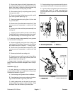
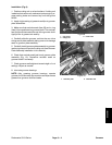
C. Connect extension spring (item 14) to stud on
groomer plate. Make sure that spring is in the stud
groove and thatspring hook is positioned towardthe
drive pulley.
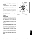
D. Secure quick--up ball joint rod to drive side
groomer plate with shoulder bolt (Fig. 6). Torque
shoulder bolt from 17 to 21 ft--lb (23 to 28 N--m).
E. Slide pulley spacer (item 2) and washer (item 3)
onto groomer shaft.
F. Apply antiseize lubricant to square keys (item 4)
that locate drive and driven pulleys. Position keys
into shaft slots.
NOTE: To prevent cutting reel from turning when
installing drive pulley, block cutting reel with piece of
wood.
G. Apply Loctite #242 to threads of flange head
screw that secures drive pulley to pivot hub shaft.
Slide drive pulley onto shaft and secure with flange
head screw. Torque screw from 27 to 32 ft--lb (37 to
43 N--m).
NOTE: To preventgroomer shaft from turning when
installing drivenpulley, usewrench ongroomer shaft
flats.
H. Slide driven pulley onto groomer shaft and se-
cure with flange nut. Torque flange nut from 17 to 21
ft--lb (23 to 28 N--m).
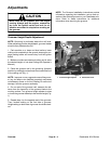
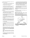
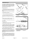
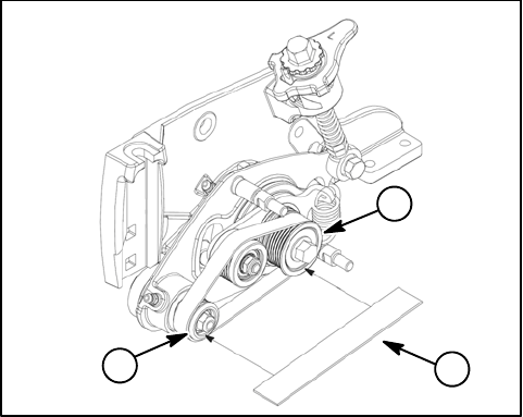
I. Check pulley alignment by laying a straight edge
along the outer face ofthe drive pulley (Fig. 7). Drive
and driven pulleys should be in line within 0.030”
(0.76 mm). If necessary, align pulleys by removing
driven pulley and installing or removing washer(s)
(item 3) between pulley and pulley spacer.
J. After pulleys are aligned, install groomer drive
belt and groomer belt cover (see Groomer Belt Re-
placement in this section).
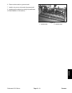
4. Check that excluder seals just touch groomer plate
assembly. Reposition excluder seals on groomer shaft
if necessary.
5. Checkgroomerreelheightandmowerheight--of--cut
settings. Adjust as needed.
6. Lubricate groomer bearings.
NOTE: After greasing groomer bearings, operate
groomer for30seconds, stopmachine andwipe excess
grease from groomer shaft and seals.
1. Drive pulley
2. Driven pulley
3. Straight edge
Figure 7
2
1
3