


Reelmaster 5010 Series Hydraulic System (Rev. C)Page 4 -- 11
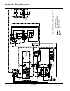
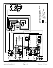
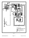
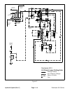
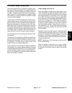
Mow Circuit
A four section gear pump is coupled to the piston (trac-
tion) pump. Gear pump sections (P1) and (P2) supply
hydraulic flow for the mow circuit. These gear pumps
take their suction from the hydraulic reservoir.
The mow control manifold contains two independent
control circuits for the front and rear cutting units. Each
circuit is supplied by its own pump section. Pump sec-
tion (P1) supplies hydraulic power to the rear cutting
units throughmowcontrolmanifold portP1,solenoid re-
lief valve (MSV1) anddirection valve (MR1). Pump sec-
tion (P2) supplies the front cutting units through
manifold port P2, solenoid relief valve (MSV2) and di-
rection valve (MR2). Both circuits share manifold port T,
which drains to the oil cooler, oil filter and hydraulic res-
ervoir.
On the mow circuit supplied by pump section (P1) (rear
cutting units), maximum system pressure is limited by
solenoid relief valve (R1), which is set at 2500 PSI (172
bar). On the circuit supplied by pump section (P2) (front
cutting units), maximum system pressure is limited by
solenoid relief valve (R2), which is set at 3500 PSI (241
bar).
OnReelmaster5510and5610machines,allcuttingreel
motors areequippedwith crossover reliefvalves topre-
vent hydrauliccomponent damagein casea cuttingreel
should stall.
The Electronic Control Module (ECM) uses inputs from
various machine switches to determine when solenoid
relief valves (MSV1) and (MSV2) are to be energized.
The ECM also provides a slight delay in activation of
front and rear cutting units.
Whensolenoid reliefv alves (MSV1)and(MSV2) arenot
energized (PTO switch in the OFF position), flow from
pump sections (P1) and (P2) is directed out the mow
manifold port T and returns to the hydraulic reservoir,
by--passing the reel motors.
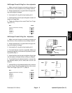
Mow (Fig. 10)
When solenoid valve (MSV1) is energized by the ECM,
pumpsection(P1)flowentersmowcontrolmanifoldport
P1 and is directed to reel speed control valve (FC1).
Flow through the speed control valve is pressure com-
pensated by logic cartridge valve (EP1). The logic c ar-
tridge valve maintains a pressure of 75 PSI (5.2 bar)
across the speed control valve. Any excess flow is re-
turned to the hydraulic reservoir. Regulated flow contin-
ues through valve (MR1) and out to the rear reel motors
to rotate the cutting reels. When valve (MR1) is in the
Mow position, therear reels rotate correctly for mowing.
Returnoil fromthe rearreelmotorsis directedtothe res-
ervoir through valve (MR1) and manifold port T.
Mow circuit pressure for the rear cutting units (pump
section P1) can be measured at manifold port G1.
When solenoid valve (MSV2) is energized by the ECM,
oil flow from port P2 is directed through reel speed con-
trol valve(FC2). Flow throughthe speed control valveis
pressure compensated by logic cartridge valve (EP2).
The logic cartridge valvemaintains apressure of 75PSI
(5.2 bar) across the speed control valve. Any excess
flow is returned to the hydraulic reservoir. Regulated
flow continues through valve (MR2) and out to the front
reel motors. When valve (MR2) is in the Mow position,
the front reels r otate correctly for mowing. Return oil
from the front motors isdirected to the reservoir through
valve (MR2) and manifold port T.
Mow circuit pressure for the front cutting units (pump
section P2) can be measured at manifold port G2.
Backlap
During the backlap mode of operation, the reel circuits
operate the same as in the Mow mode. When either
valve (MR1) or (MR2) is set to the Backlap position, the
valvereversesthedirectionofhydraulicflowthroughthe
rear or front reel motors allowing the backlap operation.
Hydraulic
System