


Reelmaster 5010 Series Hydraulic System (Rev. C)Page 4 -- 91
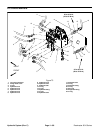
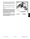
For lift control manifold service procedures, see Mow
Control Manifold Service in this section. Refer to Figure
77 for cartridge valve installation torque. Refer to Fig-
ures77and78forhydraulicfitting installationtorqueval-
ues.
NOTE: Solenoid valves SV1 and SV2 on the lift control
manifolduseacoil spacerbetweenthesolenoidcoiland
nut.
NOTE: Adjustment of Relief Valve (R7) is NOT recom-
mended.
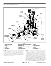
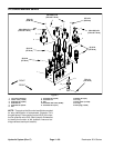
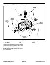
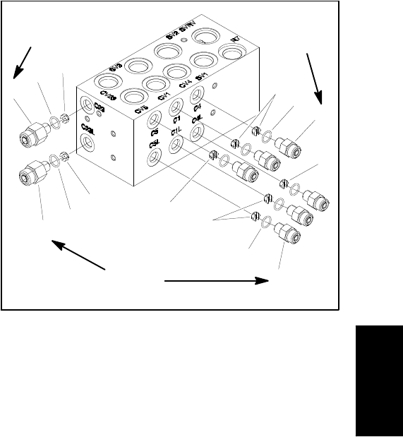
IMPORTANT: A flow control orifice is placed be-
neathseveral ofthe hydraulicfittings onthe liftcon-
trol manifold (Fig. 78). The lift manifold uses three
(3) different orifice sizes. If a fitting is removed from
the lift control manifold and an orifice is in the man-
ifold port, make sure to remove orifice and label its
position for assembly purposes.
IMPORTANT: When installing orifice in manifold
(Fig. 78), make sure that orifice is flat in the base of
the fitting cavity. Manifold damage is possible if the
orifice is cocked in the cavity.
1. Fitting (2 used)
2. O--ring
3. Orifice (0.046)
4. Orifice (0.028)
5. Fitting (6 used)
6. Orifice (0.055)
Figure 78
4
1
2
5
3
1
2
3
4
2
2
6
6
5
(17 N--m)
10 ft--lb
(17 N--m)
10 ft--lb
(17 N--m)
10 ft--lb
Hydraulic
System