


Rev. B
Reelmaster 5010 Series Hydraulic System (Rev. C)Page 4 -- 41
CAUTION
Before openinghydraulic system, operateall hy-
draulic controls to relieve system pressure and
avoid injury from pressurized hydraulic oil. See
Relieving HydraulicSystemPressure inthe Gen-
eral Information section of this chapter.
4. Raise and prop operator seat to allow access to hy-
draulic mow control manifold.
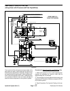
5. Set r eel speed controls (FC1 and FC2) to full open
(highest number). Make sure backlap levers are posi-
tioned in the mow position.
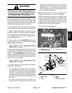
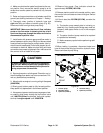
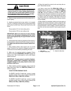
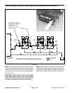
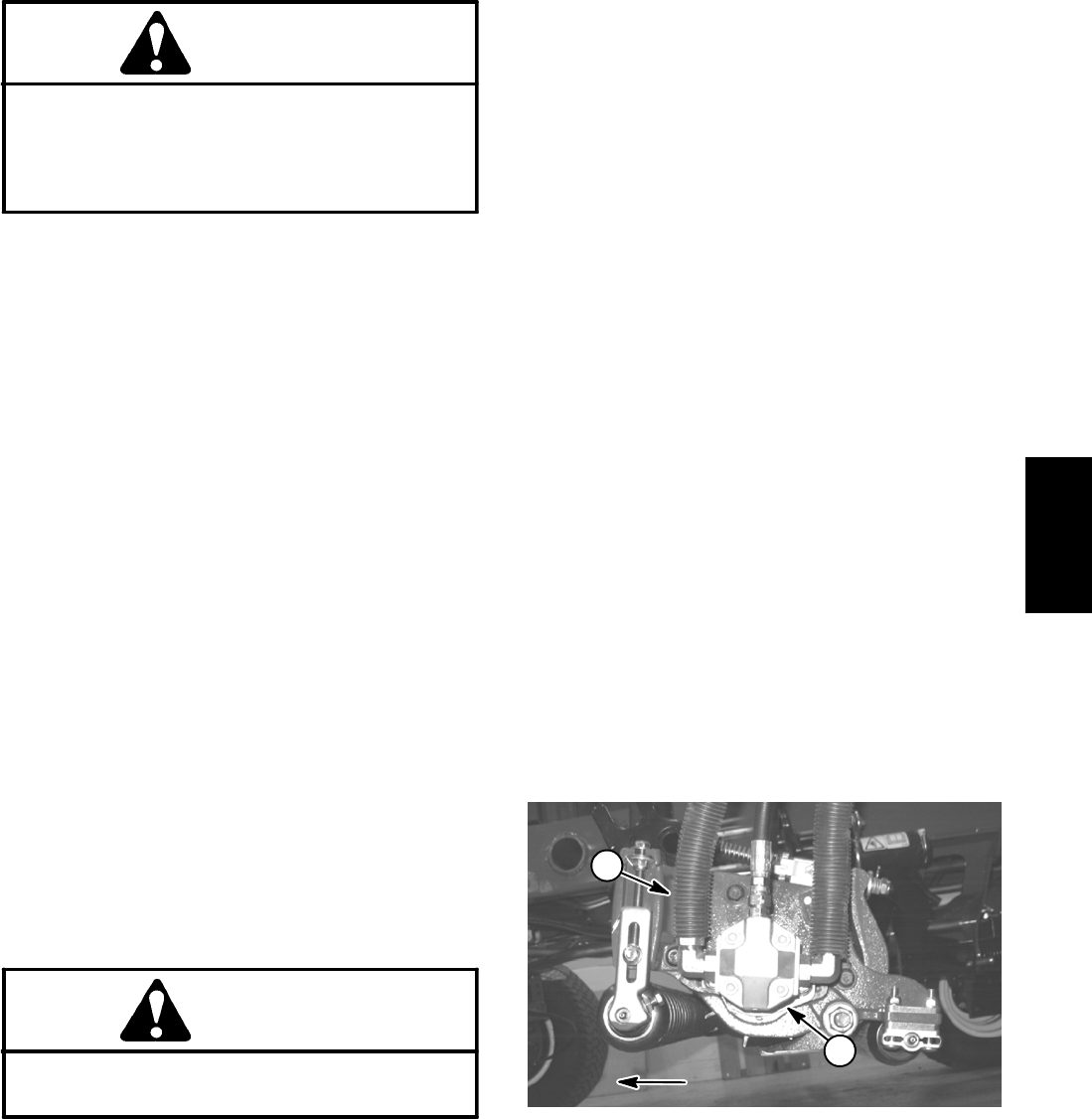
6. Thoroughlycleanjunction ofhydraulicinlet hoseand
reel motor fitting on left side cutting unit for the relief
valve to be tested. Disconnect hose from reel motor fit-
ting (Fig. 38):
Left rear cutting unit (#2) for relief valve (R1)
Left front cutting unit (#4) for relief valve (R2)
IMPORTANT: Make sure that the oil flow indicator
arrow on the flow meter is showing that the oil will
flowfrom thedisconnectedhose, throughthetester
and into the reel motor.
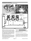
7. Install tester with pressure gauges and flow meter in
series with the disconnected hose and hydraulic fitting
on reel motor. Make sure the flow control valve on
tester is fully open.
8. After installing tester, start engine and run at idle
speed. Check for any hydraulic leakage from test con-
nections and correct before proceeding with test.
9. Move throttle to full speed (3200 RPM).
CAUTION
Keep away from reels during test to prevent per-
sonal injury from rotating reel blades.
10.Have a second person occupy seat, press PTO
switch to ON and then move Lower -- Mow/Raise lever
forward to engage cutting units.
IMPORTANT: When performing this test, do not
hold over relief any longer than necessary to obtain
pressure reading.
11.Watch pressuregauge carefully while slowly closing
the tester flow control valve.
12.As the relief valve lifts, system pressure should be:
From 2450 to 2600 PSI (169 to 179 bar) for relief
valve (R1)
From 3450 to 3600 PSI (238 to 248 bar) for relief
valve (R2)
13.Open thetester flowcontrol valve,disengagecutting
units and stop the engine.
14.If pressure is incorrect, remove solenoid valve on
mow manifold and clean or replace valve (see Mow
Control Manifold Service in the Service and Repairs
section of this chapter). Also, if pressure is still low after
solenoid valve service, check for restriction in pump in-
take line. Gear pump (P2) (front cutting unit circuit) and/
or pump (P1) (rear cutting unit circuit) could also be
suspected of wear, damage or inefficiency (see Gear
Pump (P1) and (P2) Flow Test in this section).
15.After testing is completed, make sure that engine is
stopped, then relieve hydraulic system pressure (See
Relieving Hydraulic System Pressure in the General In-
formation section of this chapter). Remove tester from
machine and connect hydraulic hose to reel motor fit-
ting.
1. Cutting reel motor (#2 shown)
2. Reel motor inlet hose
Figure 38
1
2
FRONT OF MACHINE
Hydraulic
System