


Rev. B
Reelmaster 5010 Series Page 5 -- 33 Electrical System
Mow/Transport Switch
Themow/transportswitch isanormally closedproximity
switch that opens when the mow stop lever is placed in
the transport position. The sensing plate for the mow/
transport switch is the mow s top lever. The switch on
machines with a serial number below 310000000 is dif-
ferent than the switch on machines with serial numbers
above 310000000 but the switch function is the same.
Testing
1. Before disconnecting the mow/transport switch for
testing, the switch and its circuit wiring should be tested
as an ECM input with the Diagnostic Display (see Diag-
nostic Display in the Troubleshooting section of this
chapter). Ifthe Diagnostic Displayverifies that themow/
transport switch and circuit wiring are functioning cor-
rectly, no further switch testing is necessary. If the
Diagnostic Display determines that the mow/transport
switch and circuit wiring are not functioning correctly,
proceed with testing procedure.
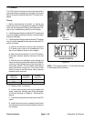
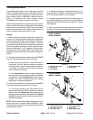
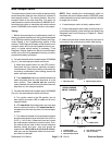
2. On machines with serial numbers below310000000
(Fig. 41), test mow/transport switch as follows:
A. Make sure ignition switch is in the OFF position.
Disconnect the wire harness electrical connector
fromthe switch.Check thecontinuity oftheswitch by
connecting a multimeter (ohms setting) across the
switch connector terminals.
B. Thereshould becontinuity (closed)between the
switch terminals when the mow stop lever is in the
mow position. There should not be continuity
(open) between the switch terminals when the mow
stop lever is in the transport position.
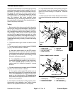
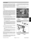
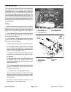
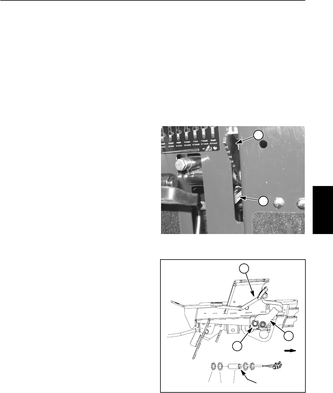
3. Onmachines with serialnumbers above310000000
(Fig. 42), test mow/transport switch as follows:
A. Turn ignition switch to the ON position (do not
start engine) and check LED on cable end of mow/
transport switch.
B. LED should be illuminated when the mow stop
lever is in the mow position. LED should not be illu-
minated when the mow stop lever is in the transport
position.
C. The distance between the mow/transport switch
andthemow/transportlevershouldbefrom0.040”to
0.100”(1.1to2.5 mm).Ifdistanceisincorrect,loosen
jam nuts that secure switch to machine frame. Posi-
tion switch with jam nuts to allow correct clearance
between switch and lever. Jam nuts should be
torqued from 162 to 198 in--lb (18.4 to 22.4 N--m).
After jam nuts are tightened, make sure that clear-
ance has not changed.
NOTE: When installing the mow/transport switch on
machines with serial numbers below 310000000, place
switch plate tab into switchmounting hole that isclosest
to target end of switch.
4. If mow/transport s witch is faulty, replace switch.
5. If the mow/transport switch tests correctly and a cir-
cuit problem still exists, check wire harness (see Wiring
Schematic and Circuit Drawings in Chapter 9 -- Electri-
cal Diagrams).
6. Make sure that wire harness electrical connector is
connected to the mow/transport switch after testing.
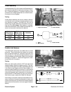
1. Mow stop lever 2. Mow/transport switch
Figure 41
1
2
SERIAL NUMBER
BELOW 310000000
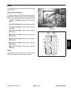
1. Traction pedal
2. Mow/transport lever
3. Mow/transport switch
4. Lock washer (2 used)
5. Jam nut (2 used)
Figure 42
SERIAL NUMBER
ABOVE 310000000
2
1
3
FRONT
LED location
34
5
Electrical
System