


Rev. B
Reelmaster 5010 SeriesPage 5 -- 22Electrical System
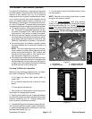
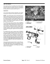
Up Limit Switch
The up limit switch is a normally open proximity switch
that closes when the cutting units are in the lowered
position. A bracket on the front, right lift arm acts as the
sensing plate for the up limit switch (Fig. 21).
Adjustment
The up limit switch should be secured to the switch
bracket at the midpoint of the bracket mounting slots.
NOTE: Thevertical locationof theup limitswitch on the
switch bracket will determine the turn--around position
of the front, outside cutting units (cutting units #4 and
#5). Raising the switch on the bracket will allow a lower
turn--around position of the cutting units. Lowering the
switch on the bracket will allow a higher turn--around
position of the cutting units.
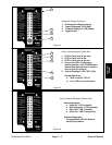
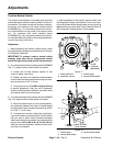
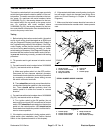
For machines with serial numbers below 310000000
(Fig. 21), the distance between the up limit switch and
sensing plate onlift arm should be from 0.048” to 0.077”
(1.2 to 1.9 mm). If distance is incorrect, loosen two (2)
lock nuts that secure switch bracket to machine frame.
Position bracket to allow correct clearance between
switchandsensingplate.Tightenlocknutstosecuread-
justment.
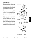
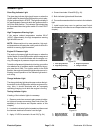
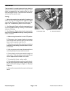
For machines with serial numbers above 310000000
(Fig. 22), the distance between the up limit switch and
the sensing plate on lift arm should b e from 0.040” to
0.100” (1.1 to 2.5 mm). If distance is incorrect, loosen
jam nuts that secure up limit switch to machine frame.
Position switch with jam nuts to allow correct clearance
between switch and sensing plate. Jam nuts should be
torqued from162 to 198 in--lb (18.4 to22.4 N--m). After
jam nuts are tightened, make sure that clearance has
not changed.
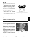
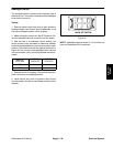
After adjustment to the uplimit switch, use the Diagnos-
tic Display (see Special Tools in this chapter) to verify
that uplimit switch andcircuit wiringare functioning cor-
rectly (see Up Limit Switch in the Component Testing
section of this chapter).
1. Lift arm
2. Up limit switch
3. Sensing plate
4. Lock nut (2 used)
5. Switch bracket
Figure 21
1
2
3
4
5
SERIAL NUMBER
BELOW 310000000
1. Up limit switch
2. Lock washer
3. Jam nut
4. Lift arm
Figure 22
SERIAL NUMBER
ABOVE 310000000
2
3
1
LED location
2
3
4
FRONT