


Rev. B
Reelmaster 5010 SeriesPage 5 -- 20Electrical System
Adjustments
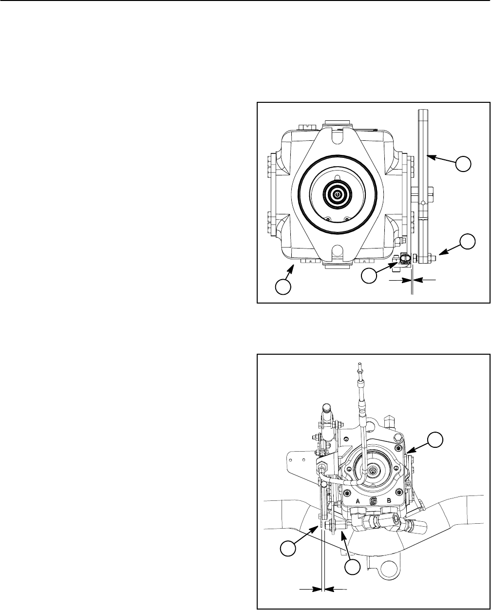
Traction Neutral Switch
The traction neutral switch is a normally open proximity
switch that closes when the traction pedal is in the neu-
tral position.The switch mountsto a bracketon the trac-
tion pump. On machines with serial numbers below
310000000 (Fig. 17), the sensing element for the trac-
tion neutral switch is a cap screw on the pump control
arm. On machines with serial numbers above
310000000 (Fig. 18), the sensing element for the trac-
tion neutralswitch is thetraction lever bracketthat is se-
cured to the pump control arm.
Adjustment
1. Before adjusting the traction neutral switch, check
andadjusttraction systemneutralposition(seeTraction
Unit Operator’s Manual).
IMPORTANT: To prevent traction neutral switch
damage, make sure that no components contact
switch throughentire pump control arm movement.
2. Formachines withserial numbersbelow310000000
(Fig. 17), adjust traction neutral switch as follows:
A. Loosen jam nut that secures position of cap
screw on pump control arm.
B. Rotate cap screw so clearance exists between
head of the screw and neutral switch body but clear-
ance is less than 0.125” (3.2 mm).
C. Torque jamnut from 71to 89 in--lb (8 to10 N--m)
to secure adjustment. After jam nut is tightened,
make sure that clearance between cap screw head
and neutral switch has not changed.
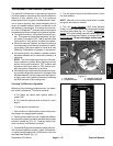
3. Formachineswithserialnumbersabove310000000
(Fig. 18), adjust traction neutral switch as follows:
A. When the traction lever is in the neutral position,
the clearance between the head of neutral switch
and the traction lever bracket should be from 0.040”
to 0.100” (1.1 to 2.5 mm).
B. If clearance is incorrect, loosen jam nuts that se-
cure neutral switch to pump bracket. Position switch
with jam nuts to allow correct clearance between
switchandtractionleverbracket.Jamnutsshouldbe
torqued from 162 to 198 in--lb (18.4 to 22.4 N--m).
After jam nuts are tightened, make sure that clear-
ance has not changed.
4. After adjustment to the traction neutral switch, use
the Diagnostic Display (see Special Tools in this chap-
ter)to verifythat tractionneutrals witch andcircuit wiring
are functioning correctly(see Traction Neutral Switchin
the Component Testing section of this chapter).
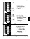
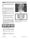
1. Pump control arm
2. Cap screw / jam nut
3. Traction pump
4. Traction neutral switch
Figure 17
1
3
2
0.125”
(3.2 mm)
4
(maximum)
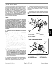
1. Traction pump
2. Traction lever bracket
3. Traction neutral switch
Figure 18
2
1
3
0.070” to 0.100”
(1.8 to 2.5 mm)