


Reelmaster 5010 SeriesGroomer Page 8 -- 12
Groomer Reel Service
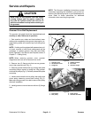
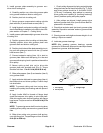
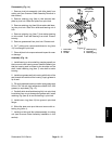
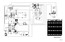
Inspect groomer reel blades frequently for damage and
wear.Straightenbentbladeswithapliers.Eitherreplace
worn blades or reverse the blades to put the sharpest
blade edgeforward (Fig.11).Blades thatare roundedto
the midpoint of the blade tip must be reversed or re-
placed for best groomer performance.
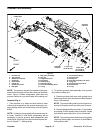
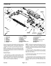
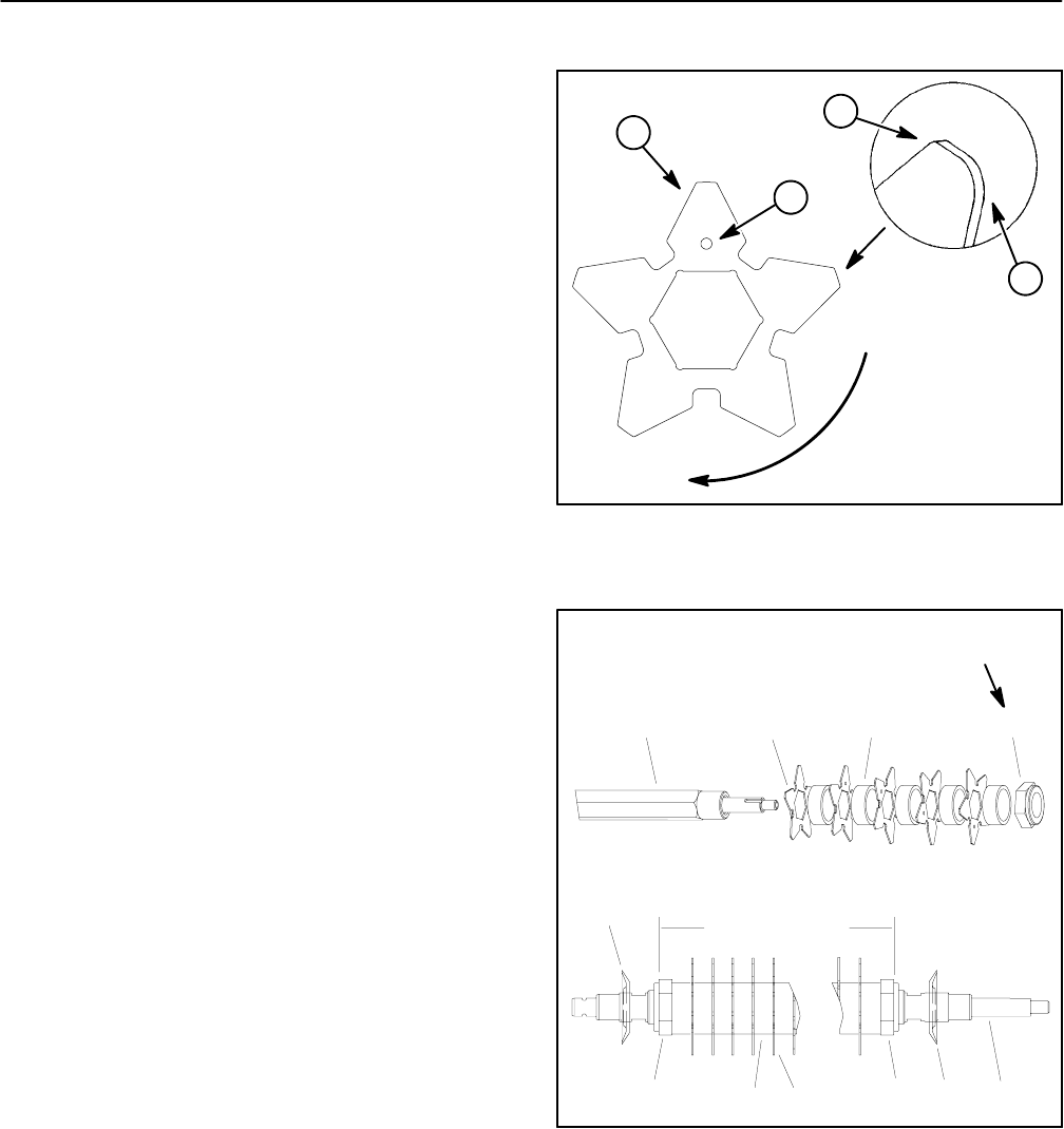
Disassembly (Fig. 12)
1. Park machine on a clean and level surface, lower
cutting units completely to the ground, stop engine, en-
gage parking brake and remove key from the ignition
switch.
2. Remove groomer reel from cutting unit (see Groom-
er Reel Removal in this section).
3. Remove excluder seals from groomer reel.
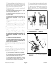
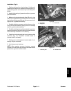
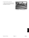
4. Ifgroomer reelisequippedwith broomerkit(Fig. 13),
remove straps and broomer brushes from reel.
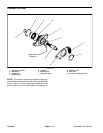
5. Remove lock nut from either end of the shaft (Fig.
12).
6. Remove spacers and blades from groomer shaft. If
needed, remove second lock nut from shaft.
7. If necessary, remove groomer shaft ends from
groomer shaft.
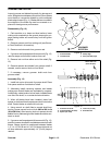
Assembly (Fig. 12)
1. Install lock nut on drive end of groomer shaft. Place
first spacer and then first blade on shaft.
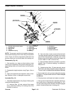
2. Alternately install remaining spacers and blades
making sure that all blades are separated by a spacer.
Additionally, rotate location holeon each installed blade
one flat of the shaft, in a counterclockwise direction.
3. When all blades have been installed, place final
spaceronshaftandthenthreadsecondlocknutontothe
shaft. Center blades on shaft with lock nuts.
4. Using wrench on shaft flats to prevent shaft from
turning, torque second lock nut from 200 to 250 in--lb
(23to28N--m). After torquing lock nut, spacers should
not befree torotate andgroomer blades shouldbe cen-
tered on shaft.
5. Ifgroomer reelisequippedwith broomerkit(Fig. 13),
positionbroomer brushestoreelblades andsecurewith
straps. Straps should be positioned between blades
1--2, 14--15, 28 --29 and 41--42. Pull straps tight and cut
off strap extension approximately 1/4” (6 mm) beyond
retainer.
1. Groomer blade
2. Location hole
3. Sharp edge
4. Dull (rounded) edge
Figure 11
ROTATION
GROOMER
3
4
2
1
1. Groomer reel shaft
2. Groomer blade (42 used)
3. Spacer (43 used)
4. Lock nut (2 used)
5. Excluder seal
Figure 12
1
2
3
4
CENTEREDONSHAFT
1
2
3
4
5
5
4
200 to 250 in--lb
(23to28N--m)