


Reelmaster 5010 SeriesPage 5 -- 34Electrical System
Backlap Switches
Thefront andrearbacklap switchesarenormally closed
ball switches that are in the normal, closed state when
the backlap lever is in the backlap position. When the
backlap lever is in the mow position, the switch opens.
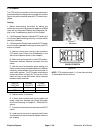
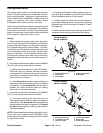
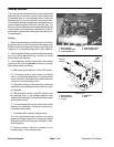
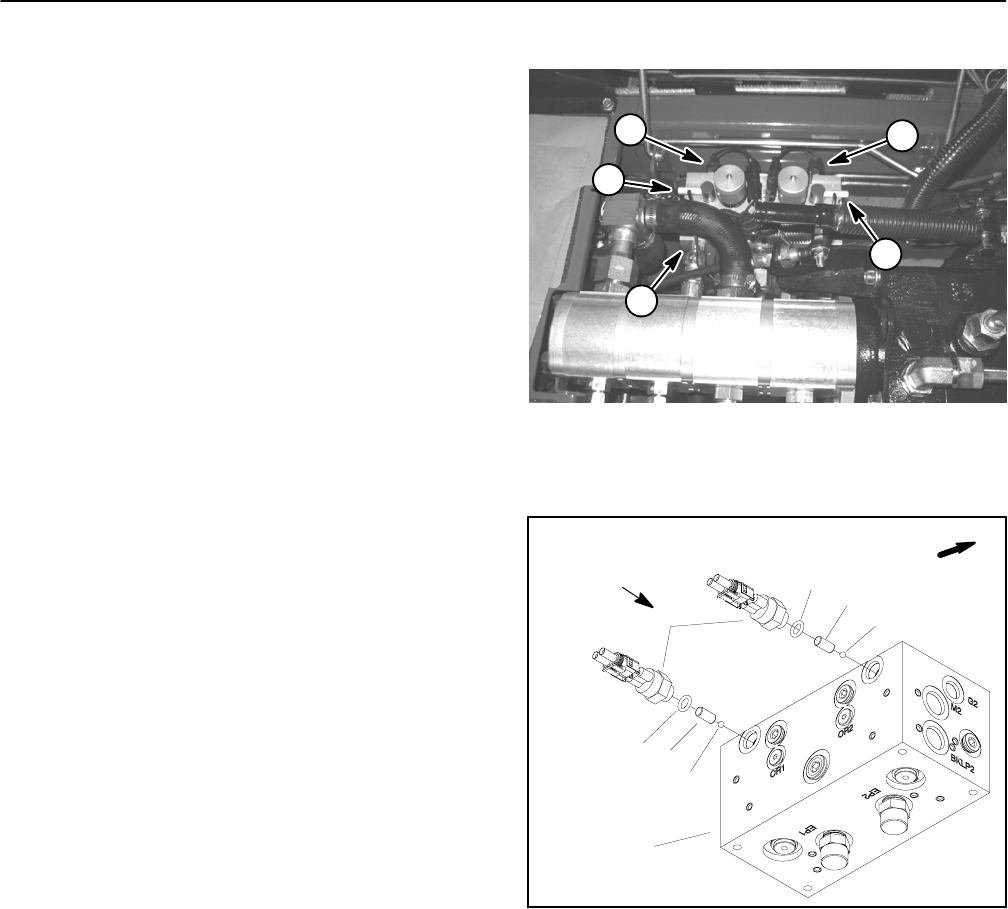
Thebacklap switchesareattachedto thehydraulicmow
control manifold located under the seat (Fig. 38). The
ElectronicControl Moduleuses the backlapswitchesas
inputs to allow only one person to backlap any of the re-
els andalsoto preventthe cuttingreels fromraising dur-
ing backlapping.
Testing
1. Before disconnecting the backlap switch for testing,
the switch and its circuit wiring should be tested as an
ECM input with the Diagnostic Display (see Diagnostic
Display in the Troubleshooting section of this chapter).
2. If the Diagnostic Display verifies that backlap switch
and circuit wiring are functioning correctly, no further
switch testing is necessary.
3. If the Diagnostic Display determines that backlap
switch and circuit wiring are not functioning correctly,
test backlap switch as follows:
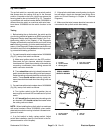
A. Make sure ignition switch is in the OFF position.
B. Tilt operator seat to gain access to backlap
switch. Locate the backlap switch on hydraulic mow
control manifold. Disconnect the harness electrical
connector from the backlap switch.
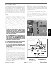
C. Checkthecontinuityoftheswitchbyconnectinga
multimeter (ohmssetting) across theswitch connec-
tor terminals.
D. With the ignition switch in the OFF position, turn
the backlap lever to the backlap position while
watching the multimeter. Continuity should be made
as the switch closes.
E. Turn the backlap lever to the mow position while
watching the multimeter. Continuity should be bro-
ken as the switch opens.
F. If backlap switch is faulty, replace switch.
G. If the neutral switch tests correctly and a circuit
problem still exists, check wire harness (see Wiring
Schematic andCircuit Drawingsin Chapter9 -- Elec-
trical Diagrams).
H. Connect harness electrical connector to the
backlap switch. Lower operator seat.
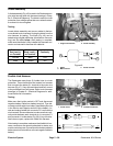
1. Mow manifold
2. Front backlap switch
3. Front backlap lever
4. Rear backlap switch
5. Rear backlap lever
Figure 38
2
3
4
1
5
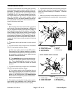
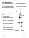
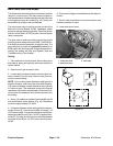
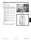
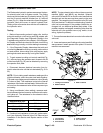
1. Mow manifold
2. Backlap switch
3. O--ring
4. Dowel pin
5. Ball
Figure 39
FRONT
2
3
4
5
1
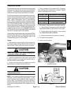
3
4
5
15 ft--lb
(20 N--m)