


Rev. B
Reelmaster 5010 Series Page 5 -- 45 Electrical System
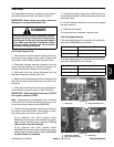
Fuel Pump
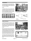
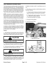
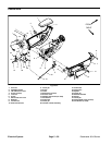
The Reelmaster fuel pump is attached to the inside of
the left side frame rail near the fuel tank (Fig. 65).
IMPORTANT: When testing fuel pump, make sure
that pump is not operated without fuel.
DANGER
Becausedieselfuelishighlyflammable,usecau-
tionwhen handlingit.Donotsmoke whiletesting
thefuelpump.Donot testfuelpumpwhileengine
is hot. Make sure that there is adequate ventila-
tion when testing. Always wipe up any spilled
fuel before starting the engine.
Fuel Pump Capacity Test
1. Park machine on a level surface, lower cutting units,
stop engine and engage parking brake. Remove key
from ignition switch. Raise operator seat and hood.
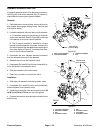
2. Disconnect harness electrical connector from the
engine fuel stop solenoid to prevent the engine from
starting (see Fuel Stop Solenoid in this section).
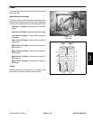
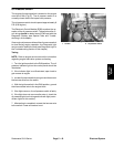
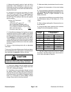
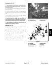
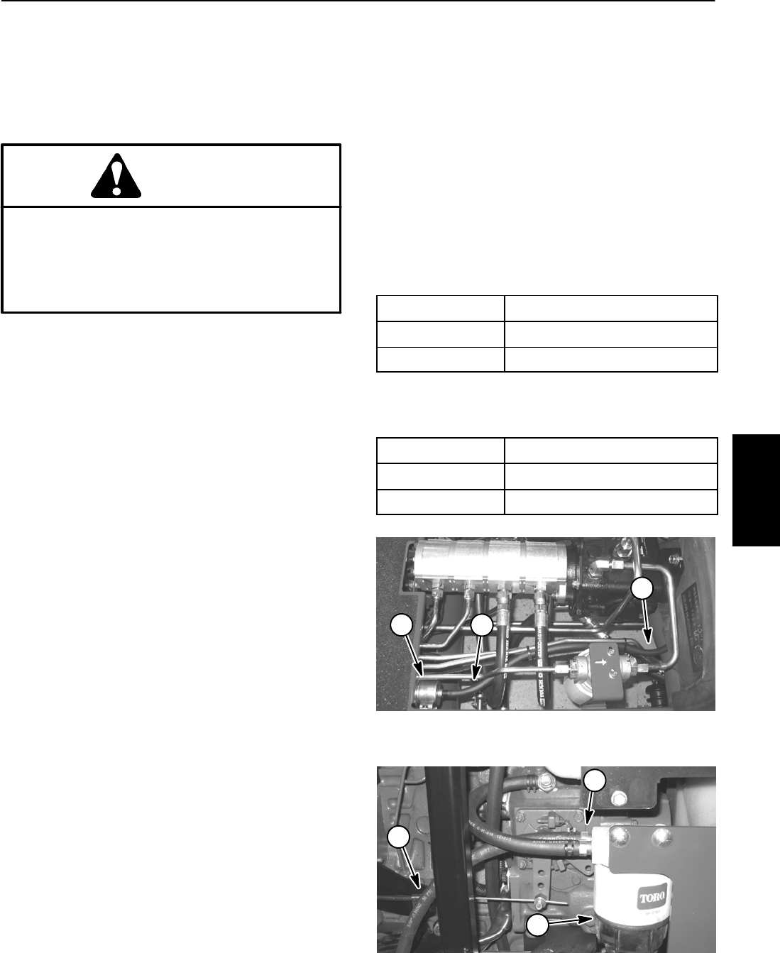
3. Disconnect fuel hose (pump discharge) from the
fuel/water separator inlet fitting (Fig. 66).
4. Make sure fuel hosesattached to the fuel pump, fuel
filter and fuel tank suction tube screen are free of ob-
structions.
5. Placedisconnected hoseinto alarge,graduated cyl-
inder sufficient enough to collect 1 quart (0.95 liter).
IMPORTANT: When testing the fuel pump, DO NOT
turn ignition switch to START.
Note: Machines that are equipped with a Biodiesel
Conversion Kit will have the same fuel pump as ma-
chines with serial numbers above 280000000.
6. Collect fuel in the graduated cylinder by turning igni-
tion switch to the RUN position. Allow pump to run for
time listed below, then return switch to OFF.
A. For machines with serial numbers below
280000000, the amount of fuel collected in thegrad-
uated cylinder should be approximately 11.8 fl oz
(350 ml) after thirty (30) seconds.
B. For machines with serial numbers above
280000000, the amount of fuel collected in thegrad-
uated cylindershould beapproximately 16fl oz(475
ml) after fifteen (15) seconds.
7. Replace fuel pump if necessary. Install fuel hose to
the fuel/water separator. Make sure to secure fuel hose
with hose clamp.
8. Connect harness electrical connector to the engine
fuel stop solenoid.
9. Bleed the fuel system.
10.Lower and secure operator seat and hood.
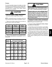
Fuel Pump Specifications
Fuel pump specifications for machines with serial num-
bers below 280000000 are as follows:
Pump Capacity
23.5 fl oz/min (700 ml/min)
Pressure 3.3 PSI (22.8 kPa)
Current Draw 0.9 amp
Fuel pump specifications for machines with serial num-
bers above 280000000 are as follows:
Pump Capacity
64 fl oz/min (1.9 liters/min)
Pressure 7 PSI (48.3 kPa)
Current Draw 2.0 amp
Figure 65
1. Fuel pump 2. Pump discharge hose
1
2
2
1. Fuel/water separator
2. Fuel hose (from pump)
3. Inlet fitting
Figure 66
1
2
3
Electrical
System