


Rev. A
Reelmaster 5010 SeriesPage 5 -- 6Electrical System
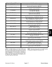
Diagnostic Display
Reelmaster 5010 machines are equipped with an Elec-
tronic Control Module (ECM) which controls machine
electrical functions. The ECM monitors various input
switches (e.g. ignition switch, seat switch, etc.) and en-
ergizes outputs toactuate solenoids or relays for there-
quested machine function.
For the ECM to control the machine as desired, each of
the input switches, output solenoids and relays must be
connected and functioning properly.
The Diagnostic Display is a tool to help the technician
verify correct electrical functions of the machine.
IMPORTANT: The Diagnostic Display must not be
left connected to the machine. It is not designed to
withstand the environment of the machine’s every
dayuse.When useoftheDiagnostic Displayiscom-
pleted, disconnect it from the machine and recon-
nect loopbackconnectorto harnessconnector.The
machine will not operate without the loopback con-
nector installed on the harness. Store the Diagnos-
tic Display in a dry, secure, indoor location, not on
machine.
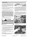
Verify Diagnostic Display Input Functions
CAUTION
The interlock switches are for the protection of
the operator and bystanders and to ensure cor-
rect operation of the machine. Do not bypass or
disconnect switches. Check the operation of the
interlockswitchesdailyfor properoperation.Re-
place any malfunctioning switches before oper-
ating the machine.
1. Park machine on a level surface, lower the cutting
units, stop the engine and engage the parking brake.
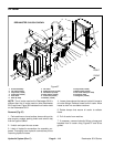
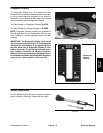
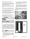
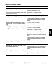
2. Open control panel cover. Locate wire harness and
connectors near ECM. Carefully unplug loop back con-
nector from harness connector (Fig. 8).
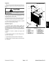
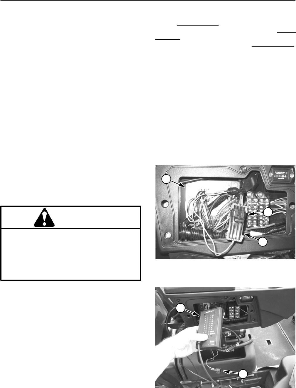
3. ConnecttheDiagnosticDisplayconnectortothehar-
nessconnector.Makesurecorrectoverlaydecalisposi-
tioned on the Diagnostic Display (Fig. 11).
4. Turn the ignition switch to the RUN position, but do
not start machine.
NOTE: The redtext on the overlay decal refers to input
switches and the green text refers to outputs.
5. The “inputs displayed
” LED,on lower rightcolumn of
theDiagnostic Display,shouldbeilluminated. If“
outputs
displayed
”LEDisilluminated,pressthetogglebuttonon
the Diagnostic Display to change to “inputs displayed
”
LED.
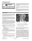
6. The Diagnostic Display will illuminate the LED
associatedwitheachoftheinputswhenthatinputswitch
is closed.Individually, changeeach oftheswitches from
open to closed (i.e., sit on seat, press traction pedal,
etc.),and notethat theappropriateLED onthe Diagnos-
ticDisplay willilluminatewhenthe correspondingswitch
is closed. Repeat on each switch that is possible to be
changed by hand.
7. If appropriate LED does not toggle on and off when
switch state is changed, check all wiring and connec-
tions to that switch and/or test switch (see Component
Testing in thisc hapter). Replace any defective switches
and repair any damaged wiring.
1. ECM location
2. Loopback connector
3. Harness connector
Figure 8
1
2
3
1. Diagnostic display 2. Loopback connector
Figure 9
1
2