


Reelmaster 5010 SeriesPage 5 -- 36Electrical System
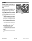
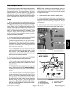
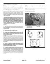
Main Power and Glow Relays
The Reelmasterelectrical systemincludes two identical
relays for current control. The main power and glow re-
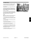
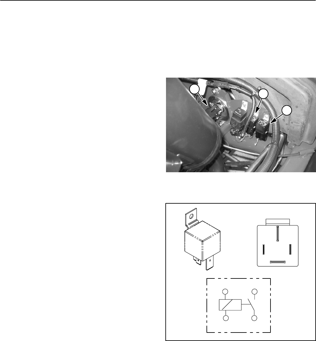
laysareattached toaframebracketunderthe hoodnext
to the hydraulic pump drive shaft (Fig. 42). Relays can
be identified by a tag on the wire harness.
The main power relay is used to provide current to the
Electronic Control Module (ECM), headlights, power
point and optionalelectric equipment. Whenthe ignition
switch is in the RUN or START position, the main power
relay is energized.
The glow relay is used to provide current to the engine
glow plugs when energized by the ECM. The ECM con-
trols and monitors the operation of the glow relay. The
glow relay and its circuit wiring should be tested as an
ECM output with the Diagnostic Display before discon-
necting and testing the relay (see Special Tools and
Troubleshooting in this chapter).
Testing
1. Park machine on a level surface, lower cutting units,
stop engine, apply parking brake and remove key from
ignition switch.
2. Open hood to gain access to relay.
3. Locate relay and disconnect the machine wire har-
ness connector from the relay. Remove relay from ma-
chine for easier testing.
NOTE: Prior to taking small resistance readings with a
digital multimeter, short the meter test leads together.
The meter will display a small resistance value (usually
0.5 ohms or less). This resistance is due to the internal
resistance of the meterand test leads. Subtract thisval-
ue from from the measured value of the component you
are testing.
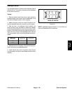
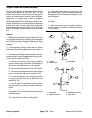
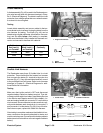
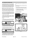
4. Verify coil resistance between terminals 85 and 86
with a multimeter (ohms setting) (Fig. 43). Resistance
should be approximately 72 ohms.
5. Connectmultimeter (ohmss etting) leadstorelay ter-
minals 30 and 87. Ground terminal 86 and apply +12
VDCtoterminal85.Therelayshouldhavec ontinuity be-
tween terminals 30 and 87 as+12 VDC is applied to ter-
minal 85. The relay should not have continuity between
terminals 30 and 87as +12 VDC is removed fromtermi-
nal 85.
6. Disconnect voltage and testleads from the relay ter-
minals.
7. Secure relay to machine and connect machine wire
harness connector to relay.
8. Lower and secure hood.
1. Pump drive shaft
2. Main power relay
3. Glow relay
Figure 42
1
3
2
Figure 43
86 87
85 30
85 86
87
30