


Reelmaster 5010 SeriesPage 3 -- 16Kubota Diesel Engine
9. Disconnect hydraulic transmission drive shaft from
engine (see Hydraulic T ransmission Drive Shaft Re-
moval in the Service and Repairs section of Chapter 4
-- Hy draulic System). Support drive shaft away from en-
gine.
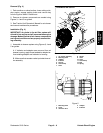
10.Disconnect wireharness connectors from the follow-
ing engine components:
NOTE: Before disconnecting wire harness connectors,
label all electrical leads for assembly purposes.
A. Alternator connector and stud.
B. Oil pressure switch located near the engine oil fil-
ter.
C. Connector, fusible link connector and positive
battery cable from the starter motor.
D. High temperature shut down switch and temper-
ature s ender located on the water pump housing.
E. Fuel stop solenoid on injector pump.
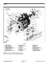
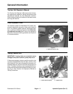
F. Negative battery cable and harness ground from
injector pump (Fig. 12).
G. Glow plug strip.
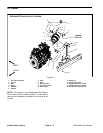
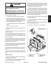
11.Remove engine from machine:
A. Attach short section of chain between lift tabs lo-
cated on each end of the c ylinder head.
B. Connect a hoist or chain fall at the c enter of the
short section of chain. Apply enough tension on the
short chain so that the engine will be supported.
C. Remove fasteners that secure the engine (with
brackets) to the engine mounts.
CAUTION
One person should operate lift or hoist while
another person guides the engine out of the ma-
chine.
IMPORTANT: Make sure to not damage the engine,
fuel hoses, hydraulic lines, electrical harness, ra-
diator,batteryor otherpartswhile removingthe en-
gine.
D. Raise engineandremovetoward front of machin-
e.
12.If necessary, remove engine brackets from engine.
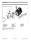
Installation (Fig. 9)
1. Locate machine on a level surface with c utting units
lowered and key removed from the ignition switch.
Chock wheels to keep the machine from moving.
2. Make sure that all parts removed from the engine
during maintenance or rebuilding are installed to the en-
gine.
3. If engine brackets were removed from the engine,
secure brackets to engine with lock washers and cap
screws. Torque cap screws from 34 to 42 ft--lb (47 to
56 N--m).
4. Install engine to m achine.
A. Attach short section of chain between lift tabs lo-
cated on each end of the c ylinder head
B. Connect a hoist or chain fall at the c enter of the
short section of chain. Apply enough tension on the
short chain so that the engine can be supported.
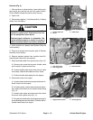
CAUTION
One person should operate lift or hoist while
another other person guides the engine into the
machine.
IMPORTANT: Make sure to not damage the engine,
fuel hoses, hydraulic lines, electrical harness, ra-
diator,batteryor otherparts while installing the en-
gine.
C. Lower engine to the machine frame. Make sure
fastener holes of the engine brackets are aligned
with the holes in the engine mounts.
D. Insert cap screw down through each engine
bracket and m ount. Place spacer, snubbing washer
and then flange nut on four (4) cap screws. Tighten
fasteners to secure engine to engine mounts.
5. Connect hydraulic transmission driveshaft to engine
(see Hydraulic Transmission Drive S haft Installation in
the Service and Repairs section of Chapter 4 -- Hydrau-
lic System).
6. Connect all wire harness connectors to correct en-
gine c omponents.