


Reelmaster 5010 Series Hydraulic System (Rev. C)Page 4 -- 77
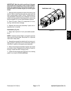
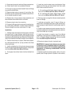
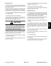
NOTE: Machines produced with serial number below
311000600 were produced with Parker brand front
wheel motors. Figure 65 shows the front axle assembly
with Parker wheel motors. Machines with serial number
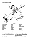
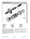
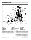
above 311000600 were produced with Eaton brand
front wheel motors. Figure 66 shows the front axle as-
sembly with Eaton wheel motors. If Parker brand wheel
motorswerereplacedforsomereason,thereplacement
wheel motors may have been Eaton brand. Wheel mo-
tors have an identification tag on them which identifies
the brand. Removal and installation of front wheel mo-
tors is very similar regardless of motor brand.
Removal
1. Parkthe machineona levelsurface, engageparking
brake, lower cutting units and stopengine. Remove key
from the ignition switch.
2. Read the General Precautions for Removing and
Installing Hydraulic System Components at the begin-
ning of the Service and Repairs section of this chapter.
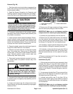
CAUTION
Before openinghydraulic system, operateall hy-
draulic controls to relieve system pressure and
avoid injury from pressurized hydraulic oil. See
Relieving HydraulicSystemPressure inthe Gen-
eral Information section of this chapter.
3. Removefront wheelfrom machine( see Front Wheel
Removal in the Service and Repairs section of Chapter
6 -- Chassis).
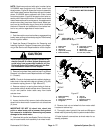
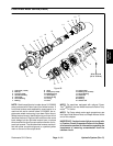
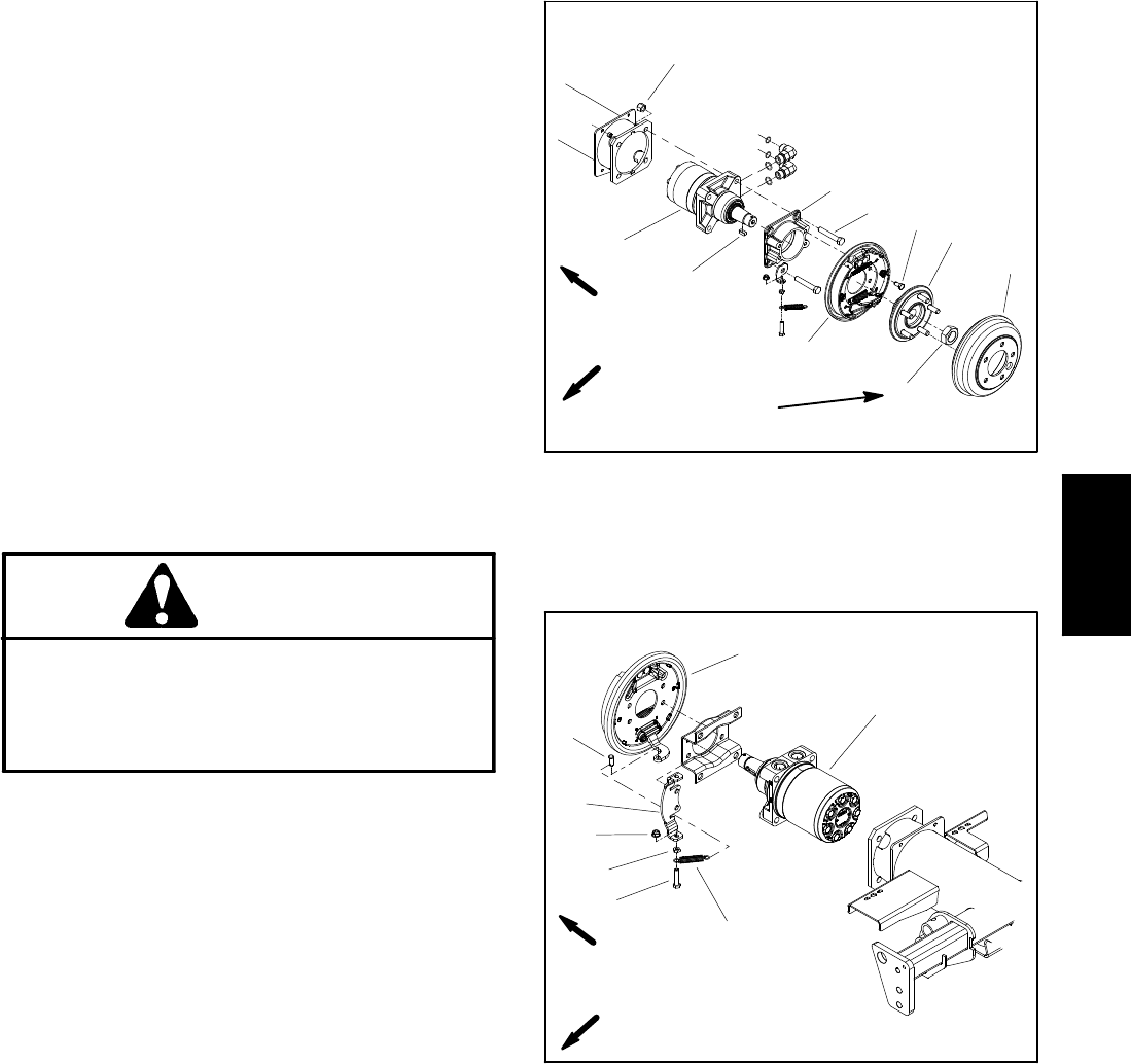
NOTE: Clevispin thatsecures brake cableto brake ac-
tuator lever is secured with cotter pin (shown in Fig. 65)
or extension spring (shown in Figs. 66 and 67).
4. Remove cotter pin or spring from clevis pin that se-
cures brake cable to brake actuator lever. Remove cle-
vis pin and position brake cable away from brake
actuator lever.
5. Remove brake drum.
6. Loosen,butdonotfullyremove,locknutthatsecures
wheel hub to wheel motor. Loosen lock nut at least two
(2) turns.
IMPORTANT: DO NOT hit wheel hub, wheel hub
puller or wheel motor with a hammer during wheel
hub removal or installation. Hammering may cause
damage to the wheel motor.
7. Usewheel hubpuller (seeSpecial Toolsin thischap-
ter) to loosen brake drum assembly from wheel motor.
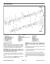
1. Brake drum
2. Lock nut
3. Wheel hub
4. Cap screw (4 used)
5. Brake assembly
6. Cap screw (4 used)
7. Brake adapter
8. Square key
9. Wheel motor (Eaton)
10. Lock nut (4 used)
Figure 66
(550 to 671 N--m)
405 to 495 ft--lb
2
3
6
8
9
10
1
5
7
4
STANDARD 2WD MACHINE WITH
EATON WHEEL MOTORS SHOWN
FRONT
RIGHT
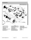
1. Brake assembly
2. Clevis pin
3. Brake spring bracket
4. Flange nut
5. Jam nut
6. Cap screw
7. Extension spring
8. Wheel motor
Figure 67
2
3
6
8
1
5
7
4
FRONT
RIGHT
8. Remove lock nut and wheel hub from motor shaft.
Locate and retrieve key.
9. Thoroughly clean hydraulic line ends and fittings on
wheelmotortopreventhydraulicsystemcontamination.
10.Label hydraulic connections at wheel motor for as-
sembly purposes.
Hydraulic
System