


Rev. C
Reelmaster 5010 Series Page 5 -- 35 Electrical System
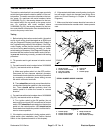
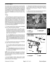
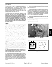
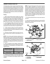
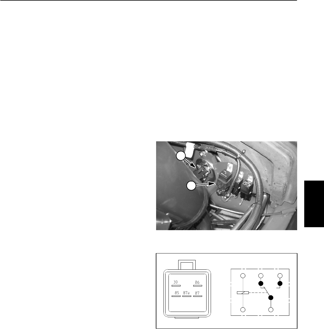
Start Relay
The start relay is used in the engine starting circuit.
When energized by the Electronic Control Module
(ECM), the start relay provides a current path to ener-
gize the engine starter solenoid. The start relay is at-
tached to a frame bracket under the hood next to the
hydraulic pump drive shaft (Fig. 45).
The ECM controls and monitors the operation of the
start relay. The relay and its circuit wiring should be
testedas anECMoutputwith theDiagnosticDisplay be-
fore disconnectingand testing therelay (see Diagnostic
Display in the Troubleshooting section of this chapter).
If the ECM has detected a malfunction in the start relay
circuit, the Diagnostic light can be used to identify the
fault (see Diagnostic Light in the Troubleshooting sec-
tion of this chapter).
Testing
1. Before disconnecting the start relay for testing, test
relay and its circuit wiring as an ECM output with the
Diagnostic Display (see Diagnostic Display in the Trou-
bleshooting section of this chapter). If the Diagnostic
Display verifiesthat therelay and circuitwiring are func-
tioning correctly, no further relay testing is necessary.
2. If the Diagnostic Display determines that start relay
and circuitwiring are notfunctioning correctly, park ma-
chineonalevelsurface,lowercuttingunits,stop engine,
apply parking brake and remove key from ignition
switch. Open hood to gain access to relay.
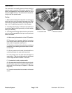
3. Locate start relay and disconnect the machine wire
harness connector from the relay. Remove relay from
machine for easier testing.
NOTE: Prior to taking small resistance readings with a
digital multimeter, short the meter test leads together.
The meter will display a small resistance value (usually
0.5 ohms or less). This resistance is due to the internal
resistance of the meterand test leads. Subtract thisval-
ue from the measured value of the component you are
testing.
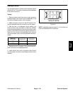
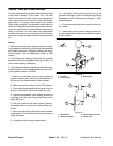
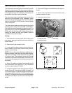
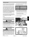
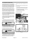
4. Using a multimeter (ohms setting), measure coil re-
sistance between terminals 85 and 86 (Fig. 46). Resist-
ance should be between 70 and 90 ohms.
5. Connectmultimeter (ohmss etting) leadstorelay ter-
minals 30 and 87. Ground terminal 86 and apply +12
VDCtoterminal85.Therelayshouldhavec ontinuity be-
tween terminals 30 and 87 as+12 VDC is applied to ter-
minal 85. The relay should not have continuity between
terminals 30 and 87as +12 VDC is removed fromtermi-
nal 85.
6. Disconnect voltage from terminal 85 and multimeter
lead from terminal 87.
7. Connectmultimeter (ohmss etting) leadstorelay ter-
minals 30 and 87A. Apply +12 VDC to terminal 85. The
relay should not have continuity between terminals 30
and 87Aas +12VDC is appliedto terminal85. The relay
should have continuity between terminals 30 and 87A
as +12 VDC is removed from terminal 85.
8. Disconnect voltage and multimeter leads from the
relay terminals.
9. Secure relay to machine and connect machine wire
harness connector to relay.
10.Lower and secure hood.
Figure 45
1. Pump drive shaft 2. Start relay
2
1
Figure 46
86
85
87A 87
30
Electrical
System