


Reelmaster 5010 Series Hydraulic System (Rev. C)Page 4 -- 75
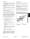
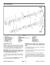
IMPORTANT: Mark the relative positions ofthe gear
teeth and the thrust plates so they can be reassem-
bledin thesameposition. Donottouch thegearsur-
faces as residue on hands may be corrosive to gear
finish.
7. Remove thethrust plates and sealsfrom each pump
section. Before removing each gear set, apply marking
dye to mating teeth to retain ”timing”. Pump efficiency
may be affected if the teethare not installed in the same
position duringassembly.Keep the partsfor each pump
section together; do not mix parts between sections.
8. Clean all parts. Check all components for burrs,
scoring, nicks and other damage.
9. Replace the entire pump assembly if parts are ex-
cessively worn or scored.
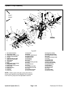
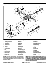
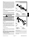
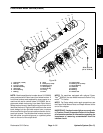
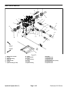
Disassembly (Fig. 63)
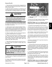
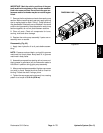
1. Apply clean hydraulic oil to all parts before assem-
bling.
NOTE: Pressureseals andback--up rings fitin grooves
machined into thrust plates. Body seals fit in grooves
machined in body faces.
2. Assemble pump sections starting at front cover end.
Apply grease or petroleum jelly to new section seals to
hold them in position during gear pump assembly.
3. Afterpump hasbeen assembled,tightencap screws
and nuts by hand. Rotate the drive shaft to c heck for
binding. Protect the shaft if using a pliers.
4. Tightenthe capscrews andnuts evenlyina crossing
pattern to a torque of 33 ft--lb (45 N--m).
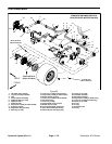
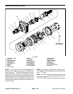
Figure 64
DIAGONAL LINE
Hydraulic
System