


Reelmaster 5010 Series GroomerPage 8 -- 7
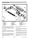
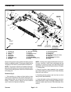
C. Remove the flange nut (item 6) that secures driv-
en pulley (item 5) to groomer shaft. Remove driven
pulley from shaft. Locate and retrieve square key
(item 4) that locates driven pulley on shaft.
D. Slide washer (item 3) and pulley spacer (item 2)
from groomer shaft.
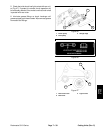
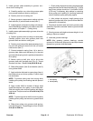
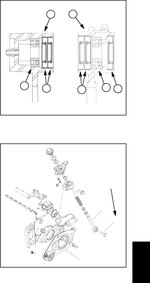
E. Remove shoulderbolt that secures quick--up ball
joint rod to groomer plate (Fig. 10).
F. Disconnect extension spring (item 14) from stud
on groomer plate.
G. Removetwo (2) socket headscrews (item 7) that
secure groomer components to cutting unit side
plate.
H. Remove pivot hub and idler plate assembly from
cutting unit.
I. Support groomer shaft to prevent it from falling.
Carefully slide drive side groomer plate from groom-
er shaft and cutting unit. Remove groomer shim.
3. To remove groomer plate assembly from groomer
non--drive side of cutting unit:
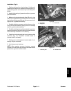
A. Remove hydraulic reel motor from cutting unit
(see Hydraulic Reel Motor Removal in the Service
and Repairs section of Chapter 7 -- Cutting Units).
B. Remove two(2) socket head screws (item 7) that
secure groomer components to cutting unit side
plate.
C. Remove pivot hub from cutting unit.
D. Support groomer shaft to prevent it from falling.
Carefully slide non--drive side groomer plate from
groomer shaft and cutting unit.
4. Inspect seals, bearings and bushing in groomer
plates. Remove and discard damaged or worn compo-
nents.
Installation (Fig. 4)
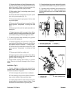
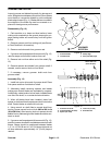
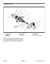
1. If seals, bearings or bushing was removed from
groomer plates, install new components noting proper
orientation as shown in Figure 5.
A. Pack bearings with grease before installation.
B. Press bearings into groomer plate so that bear-
ings contact shoulder in groomer plate bore.
C. Install grease seals so that seal lips are posi-
tioned toward the groomer blade location. Seals
should be flush with surface of groomer plate.
D. Pressbushings into groomerplate untilthe bush-
ing contacts the shoulder in the groomer plate bore.
E. If groomer studs(not shown) were removed from
groomer plate (item 17), install new studs into
groomer plate and torque from 14 to 18 ft--lb (19 to
24 N--m).
1. Drive side groomer plate
2. Non--drive groomer plate
3. Bearing
4. Grease seal
Figure 5
2
1
4
3
4
3
4
1. Groomer plate
2. Shoulder bolt
3. Quick--up ball joint rod
Figure 6
3
1
2
17 to 21 ft--lb
(23to28N--m)
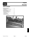
Groomer